2 mechanical overview, 1 front view, led status and behavior – Lanner FW-8892 User Manual
Page 23
FW-8892
23
2.2 Mechanical Overview
This section of the manual describes the mechanical and device
nomenclature of FW-8892.
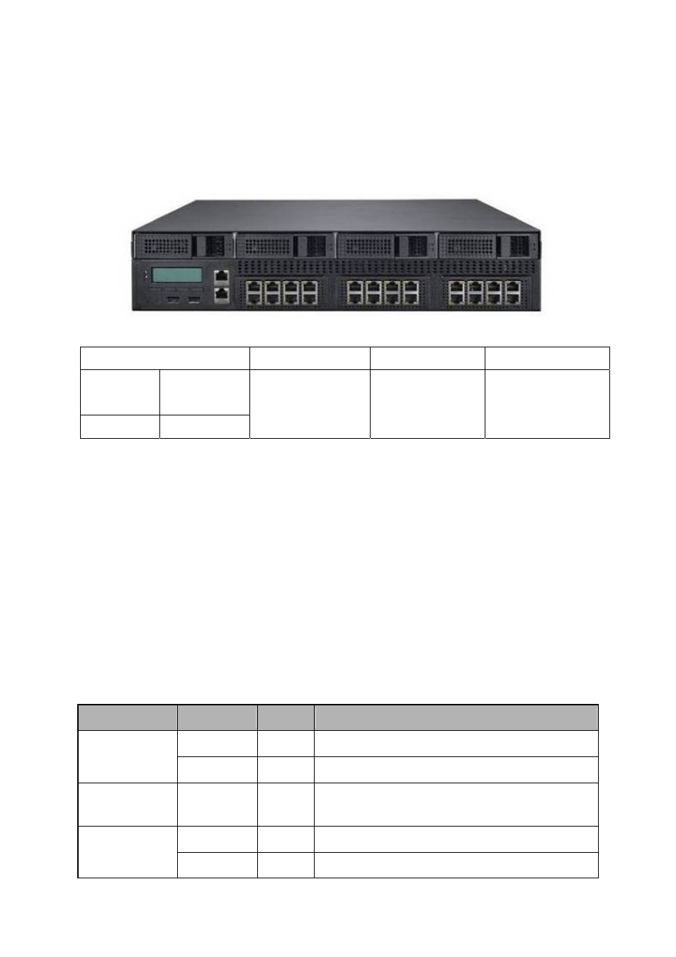
2.2.1 Front View, LED Status and Behavior
Figure 5 - FW-8892 Front View
HDD Tray
HDD Tray
HDD Tray
HDD Tray
Graphic LCM
with Button
IPMI
Management
Port (RJ45)
USB x2
Console (RJ45)
LAN Module
LAN Module
LAN Module
(1) Graphic LCM Module with buttons
(2) IPMI Management Port
(Option)
(3) Console: The console port cable connects FW-8892 to the host PC via. The
Default baud rate is 9600.
(4) USB: Support two USB devices.
(5) Four External 3.5” HDD Trays
(6) Three LAN module slots which can support Gigabit Copper (RJ-45) /
Optical (SFP) and 10G (SFP+) LAN Module. Max up to twenty-four Gigabit
Ethernet ports
The following table provides description of each LED on the FW-8892 front
panel.
LED
Color
Status
Description
Green
ON
Indicates when FW-8892 power is switched ON.
POWER
N/A
OFF
No power connected
STATUS
Green
Orange
Lanner Provide the Sample Codes(Please
reference the Driver/ Manual CD, under “LED
Status” for more information)
Yellow
ON
Hard disk is being accessed
HDD
N/A
OFF
No Data is being accessed