Chapter 3, Motherboard information – Lanner FW-8877 User Manual
Page 21
15
Motherboard Information
Chapter 3
Network Application Platforms
Note: A 2x6 pin (2.0”) header (J1) on the OPMA
card is provided as an VGA interface connector.
J27: A reset switch to switch between hardware and
software reset function for the front panel reset button.
A hardware reset function will reset the whole system
while a software reset function will reset the designated
software to its default value.
OPEN1: Case open detection jumper. Use this to
detect case open event.
J24: Clear CMOS Jumper. Use this jumper to reset the
BIOS setting to its factory default.
TTL1: Redundant power Supply TTL (time-to-live)
signal. It detects and reads the operating status of the
power supply.
3 2 1
and white-latched slots is configured as one
channel.
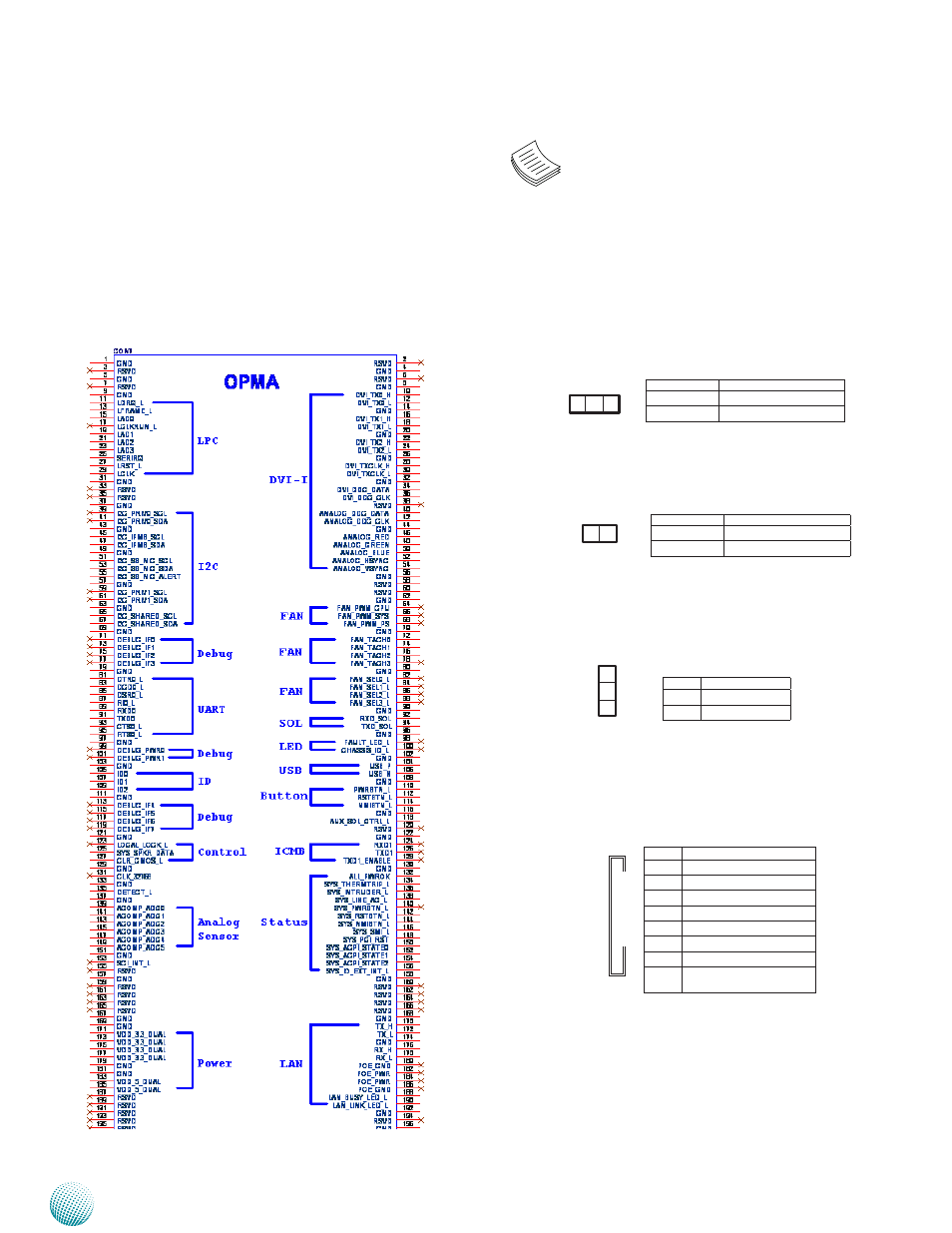
OPMA1: OPMA Connector. The OPMA connector
is for connecting the OPMA card. When the OPMA card
is connected, the management port will comply with
the Intelligent Platform Management Interface (IPMI)
standard.
Pin No.
Description
1-2
Hardware Reset
2-3
Software Reset
Pin No.
Description
1
GROUND
2
CSOPEN_N
Pin No.
Description
1-2 Normal (default)
2-3
Clear CMOS
3
2
1
2 1
Pin No.
Description
1
RDPW_TTL1
2
RDPW_TTL2
3
RDPW_TTL3
4
GND
5
6
SMB_PS_CLK
7
SMB_PS_DATA
8
I P Q _ S M L 1 _ P M B U S _
ALERT_N
1
8