Chapter 2, Chapter 2: hardware setup, Hardware setup – Lanner FW-8877 User Manual
Page 12: Preparing the hardware installation
6
Hardware Setup
Chapter 2
Network Application Platforms
Chapter 2:
Hardware Setup
Preparing the Hardware Installation
To access some components and perform certain service
procedures, you must perform the following procedures
first.
WARNING: To reduce the risk of personal injury,
electric shock, or damage to the equipment,
remove the power cord to remove power from the
server. The front panel Power On/Standby button
does not completely shut off system power.
Portions of the power supply and some internal
circuitry remain active until AC power is removed.
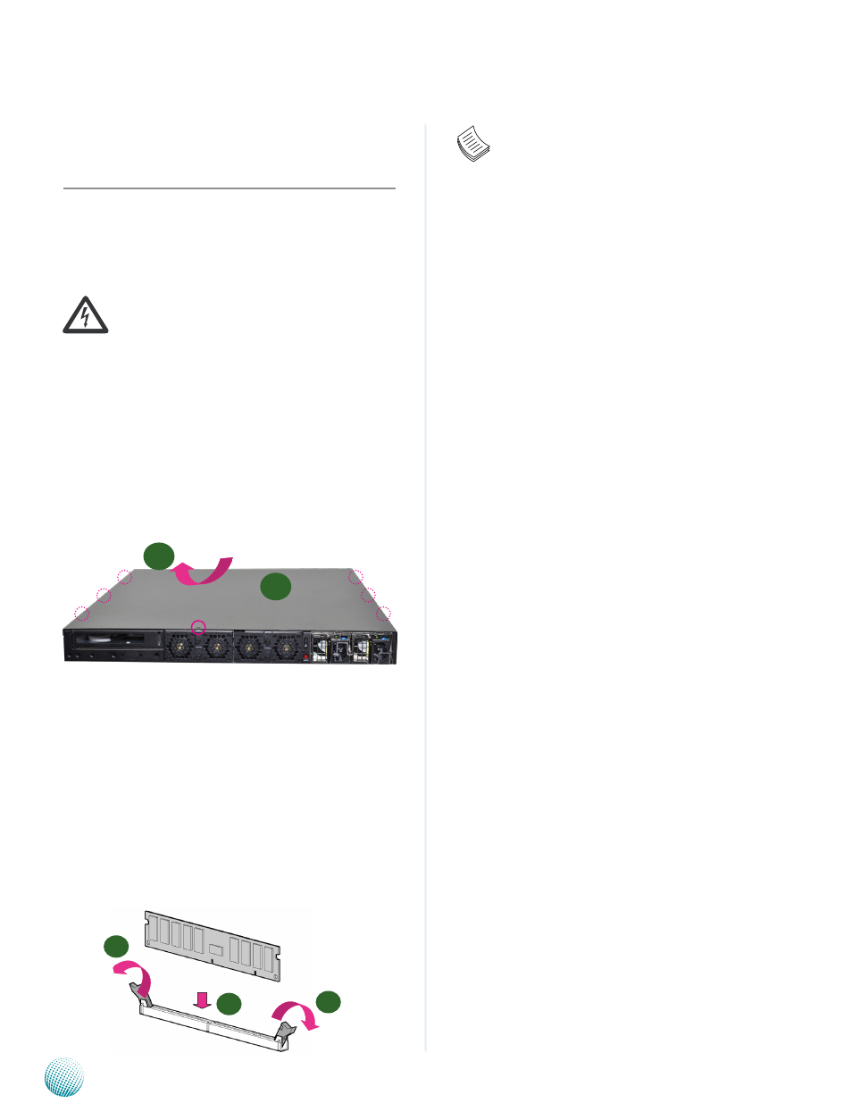
Unpower the FW-8877 and remove the power cord.
1.
Unscrew the 7 chassis screws on the top cover of the
2.
FW-8877 System.
Slide the cover backwards and open the cover.
3.
Installing the System Memory
The motherboard supports DDR3 memory to meet the
higher bandwidth requirements of the latest operating
system and Internet applications. It comes with Quad-
Channel DDR3 Dual Inline Memory Modules (DIMM)
sockets.
Open the DIMM slot latches.
1.
Install the DIMM.
2.
Note:
The motherboards can support up to 64 GB
1.
memory capacity in maximum (registered and
ECC).
Since the system is capable of
2.
Quad Channel
configuration, some installation guidelines have
to be followed to enable Quad Channel mode:
To insert 4 DIMMs on the system, insert DIMMS
into the 4 slots with black latches. And use slots
with white latches if more slots are required.
To activate Dual Channel instead of Quad
3.
Channel in the system, populate any 2 slots
with black latches. And then use slot with white
latch that belongs to the same channel as the
populated slot with black latch for any additional
DIMMs.
Starting from the board edge, one pair of black
4.
and white-latched slots is configured as one
channel.
1
2
1
unscrew the thumbscrews on
the back and open the top
cover.
2
1