Chapter 2: hardware setup, Preparing the hardware installation, Installing the system memory – Lanner FW-8756 User Manual
Page 8: Installing the hard disk, Chapter 2, Introduction
5
Introduction
Chapter 2
Network Application Platforms
Chapter 2:
Hardware Setup
Preparing the Hardware Installation
To access some components and perform certain service
procedures, you must perform the following procedures
first.
WARNING: To reduce the risk of personal injury,
electric shock, or damage to the equipment,
remove the power cord to remove power from the
server. The front panel Power On/Standby button
does not completely shut off system power.
Portions of the power supply and some internal
circuitry remain active until AC power is removed.
Unpower the FW-8756 and remove the power cord.
1.
Unscrew the screws (three on each side and two on
2.
the rear) from the top cover of the FW-8756 System.
Slide the cover backwards and open the cover
3.
upwards.
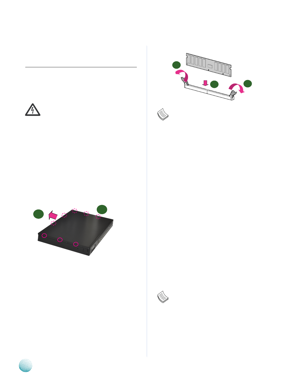
Installing the System Memory
The motherboard supports DDR3 memory that features
data transfer rates of 800, 1066, and 1333 MHz to meet the
higher bandwidth requirements of the latest operating
system and Internet applications. It comes with two
Double Data Rate three (DDR3) Dual In-line Memory
Modules (DIMM) sockets.
Open the DIMM slot latches.
1.
Install the DIMM.
2.
Note:
All DIMMs installed must be the same speed
1.
(DDR3 800, 1066, or 1333). Do not install DIMMs
supporting different speeds.
Installing the Hard Disk
The system can accommodate two 2.5” or one 3.5” Serial-
ATA disks. Follow these steps to install a hard disk into the
FW-8756:
Unscrew the 4 screws on the hard disk tray to take out
1.
the hard disk tray from the system.
Place hard disk on the hard disk tray and align the holes
2.
of the hard disk with the mounting holes on the tray.
Secure the hard disk with 4 mounting screws on the
3.
hard disk tray.
Connect the Serial-ATA power and data disk cables
4.
to the hard disk’s power and drive connectors
respectively.
Plug the Serial-ATA cable to the Serial-ATA Connector
5.
on the main board.
Repeat steps 2 to 5 to install a second disk (if there is
6.
one).
Put the hard disk tray with the installed hard disk back
7.
to the system and secure it with the mounting screws.
Note:
The 3.5” disk tray also supports 2.5” HDD
1.
installation. To do this, take off one side of the
tray first to make room for SATA cables. Attach the
HDD to the tray by fixing the screws to the slot
on the bottom of the tray.
FW-8756 SKU B can support
2.
only the 2.5” HDD.
1
2
1
2
3