Motherboard layout, Chapter 3, Motherboard information – Lanner FW-8756 User Manual
Page 12
9
Motherboard Information
Chapter 3
Network Application Platforms
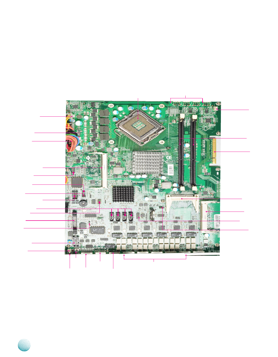
USB Connector
Motherboard Layout
The motherboard layout shows the connectors and
jumpers on the board. Refer to the following picture
as a reference of the pin assignments and the internal
connectors.
CF Card Connector
Ethernet Ports
USB2.0 Ports
VGA Cable Connector
Clear CMOS
Reset Switch
Keyboard and Mouse
Connectors
PCI-Ex8 golden finger
Mini-PCI Connector
Fan3 Fan 2 Fan 1 Fan 4
Connectors
DIMM Socket
Fan5 Connector
Serial Cable Connector
CPU Socket
4 Pin ATX Power Con-
nector
LPC1/Port 80 Pin Header
SPI ROM Update
HW/SW Reset
Power Button connector
24 Pin ATX Power
Connector
Management Port
AT Mode Power Button Con-
nector
Console Port
OPMA Connector
AT/ATX Mode Selection Jumper
Front Panel LCD Connector
SATA Connector
AT Mode Selection Jumper
- LVC-2000 (39 pages)
- LVC-5000(N4) (42 pages)
- LVC-5550S (41 pages)
- LVC-5570 (48 pages)
- LVC-5770 (49 pages)
- FW-6432 (16 pages)
- FW-7525 (41 pages)
- FW-5330 (38 pages)
- FW-6486 (18 pages)
- FW-6436 (19 pages)
- FW-7573 (44 pages)
- FW-7568 (52 pages)
- FW-7540 (47 pages)
- FW-8759 (47 pages)
- FW-7581 (23 pages)
- FW-8758 (42 pages)
- FW-7610 (44 pages)
- FW-7575 (48 pages)
- FW-8760 (53 pages)
- FW-8877 (46 pages)
- FW-8892 (58 pages)
- FW-8893C (49 pages)
- FX-3411 (48 pages)
- FW-8894 (31 pages)
- FW-8771 (47 pages)
- RS12-38800 (64 pages)
- MR-320 (20 pages)
- FX-3210 (54 pages)
- MR-301 (16 pages)
- MR-350 (12 pages)
- MR-330A (16 pages)
- MR-730 (18 pages)
- VES-220 (19 pages)
- VES-270 (19 pages)
- VES-310 (15 pages)
- VES-310 V2 (20 pages)
- VES-500 (21 pages)
- EM-F345 (30 pages)
- VES-8X2 (16 pages)
- VES-8X6 (17 pages)
- LEC-2026 (67 pages)
- LEC-2010 (65 pages)
- LEC-2136 (20 pages)
- LEC-2050 (38 pages)