Jumper settings, Chapter 3, Motherboard information – Lanner FW-8756 User Manual
Page 13
10
Motherboard Information
Chapter 3
Network Application Platforms
Note: To configure your Hard disk using the
integrated AHCI/RAID functionality, the Intel®
Matrix Storage Manager software has to be
installed on your Operating System. Visit the Intel
support page at
or more
information and download links. Operating
systems other Microsoft Windows Vista and
Microsoft Windows 7 require to pre-install the
Intel Rapid Storage Technology driver during the
F6 installation of Windows setup (“Press F6 if you
need to install a third party SCSI or RAID driver...”).
The Intel controller hubs are also supported by
Linux. Beginning with Linux kernel version 2.6.27,
the mdadm utility 3.0 supports RAID 0, RAID 1,
RAID 10, and RAID 5.
To use the RAID features in dmraid and mdadm,
you will need to set up the RAID volume using the
Intel® Matrix Storage Manager option ROM (click
CTRL + I when prompted during boot to enter the
option ROM user interface).
LPC I/O bus (Low Pin Count 1 bus): It is an Intel
proprietary connector for connecting a checkpoint
device to output checkpoints throughout booting and
Power-On Self Test (POST) to indicate the task the
system is currently running. It can also be called port 80
for outputing debugging messages.
Front LCD Module Connector(J11): The 24-pin
connector is for connecting the front system panel. Refer
to Appendix C for a simple demostration of the LCM
implementation.
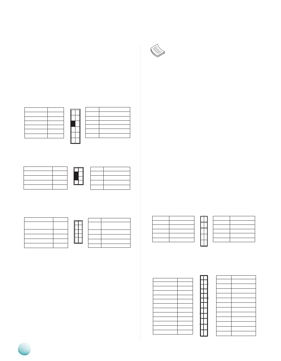
Jumper Settings
ATX Power Connector(ATX1, ATX2): These 4-pin and
24-pin connectors are for connecting ATX power supply
plugs. Find the proper orientation when inserting the
plugs, for the supply plugs are designed to fit these
connectors in only one orientation.
VGA Interface (J1): It is for connecting the VGA
interface cable.
Keyboard and mouse interface Connectors(PKMB1): It
is for connecting the PS/2 keyboard and mouse interface
cable.
USB Connector(J12) : It is for connecting the USB
module cable. It complies with USB2.0 and support up
to 480 Mbps connection speed.
SATA 1 and 2 Connectors(J6, J7, J8, J9): It is for
connecting a 2.5’’ SATA harddisk to be served as your
system’s storage. The system can support up to 2 disks
for 2.5" or 1 for 3.5" in maximum. The system’s BIOS
supports 3 modes of SATA configuration, i.e., IDE, RAID, and
AHCI. The ICH7R provides hardware support for Advanced
Host Controller Interface (AHCI) which is a programming
interface for SATA host controllers. AHCI provides advanced
performance and usability enhancements with SATA such
as Hot-Plug, no master/savle designation for SATA devices
and native command queuing.
Pin No.
Function
11
DDC-Data
9
VSYNC
7
HSYNC
5
Blue
3
Green
1
Red
Function
Pin No.
DDCCLK
12
GND
10
GND
8
GND
6
GND
4
GND
2
11
9
7
5
3
1
12
10
8
6
4
2
Pin No.
Function
9
USB Port#1
Ground
7
Ground
5
USBD0+
3
USBD0-
1
USB_VCC
Pin No.
Function
USB Port#2
Ground
10
Ground
8
USBD1+
6
USBD1-
4
USB_VCC
2
9
7
5
3
1
10
8
6
4
2
1
3
5
7
9
2
4
6
8
10
Pin No.
Function
2
LPC_AD1
4
LPC_AD0
6
VCC
8
GND
10
GND
Pin No.
Function
1
CLK
3
PLTRST#
5
LPC_FRAME_N
7
LPC_AD3
9
LPC_AD2
Pin No.
Function
2
MSCLK
4
KEY
6
KEY
8
KBCLK
Pin No.
Function
VCC
1
MSDATA
3
KBDATA
5
GND
7
2
4
6
8
1
3
5
7
Function
Pin No.
VCC
1
LSTIN-
3
LAFD-
5
LPD1
7
LPD3
9
LPD5
11
LPT7
13
LCD
15
K1
17
K3
19
GND
21
GPIO
23
Pin No.
Function
2
IOGND
4
VEE
6
LINIT-
8
LPD0
10
LPD2
12
LPD4
14
LPD6
16
VCC
18
K2
20
K4
22
VCC3
24
VCC3
1
3
5
7
9
11
13
15
17
19
21
23
2
4
6
8
10
12
14
16
18
20
22
24