Jordan Valve 1051M Series Rotary Actuator User Manual
Page 6
-6-
Disassembly cont'd,
Warning: The diaphragm plate (Key 1) may be lodged
against the diaphragm rod (Key 22), preventing the
spring compression from being relieved as the cap
screw (Key 24) is being loosened. If this is the case,
loosen the cap screw (Key 24) one full turn, and then
tap the underside of the diaphragm head until it fol-
lows the cap screw disassembly. Failure to check
for and rectify this situation prior to removing the
cap screw (Key 24) could cause a sudden release of
spring compression as the cap screw is disengaged.
This sudden release could result in personal injury or
property damage.
11.
Slowly remove the cap screw (Key 24) while
ensuring that the diaphragm head is following
the cap screw disassembly. The spring
load will be zero before the cap screw is
completely removed. The remaining parts of the
assembly can then be separated.
12.
Unscrew the cap screws (Key 32) and remove
the actuator housing assembly (Key 17).
13.
Unbolt the mounting yoke (Key 35) from the
valve body.
14.
Push out the bushing (Key 34) from the mount
ing yoke and examine for wear. Replace
if necessary.
Assembly
These instructions assume that the actuator was com-
pletely disassembled. If the actuator was only partially
assembled, start the instructions at the appropriate step.
Refer to Figures 6 & 7 for Key Numbers.
1.
If the bushing (Key 34) was replaced, press in
the new bushing and ensure the end of
the bushing is flush with the bottom of
the recess in the mounting yoke (Key 35).
2.
Slide the mounting yoke (Key 35) over the valve
shaft and secure it to the valve using the
valve mounting cap screws. Refer to
Table 3 and to the appropriate valve manual for
bolting torques on these cap screws.
Note: Exceeding the torque requirement may result
in unsafe operation of the actuator. Refer to Table 1
for recommended bolting torques.
3.
Consult Figures 2 and 3 for the desired housing
orientation. Secure the housing to the
yoke using cap screws (Key 32).
4.
Coat the thread of the cap screw (Key 24) as
well as the tapered end of the diaphragm rod
(Key 22) with an appropriate lubricant.
5.
Assemble the following parts: diaphragm rod
(Key 22), spring seat (Key 19), spring
(Key 21) and diaphragm plate (Key 1),
then secure with the cap screw (Key 24).
Tightening the cap screw will compress the
spring. Ensure that the tapered end of the
diaphragm rod is seated in the corresponding
hole in the diaphragm plate, that the spring
is seated in the spring seat, and that the cap
screw is tightened to the torque specified
in Table 1.
6.
Install the hex nut (Key 18), turnbuckle (Key 16),
hex nut (Key 14) and rod end bearing (Key 13)
onto the diaphragm rod.
7.
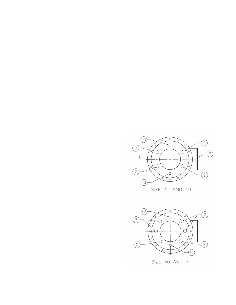
Ensure the travel stops (Key 43) are located as
shown in Figure 5.
8.
Install the diaphragm plate and attached parts
into the actuator.
Figure 5: Travel Stop Orientation
1051M S
erieS
r
otary
a
ctuator