Jordan Valve 1051M Series Rotary Actuator User Manual
Page 4
-4-
Turnbuckle Adjustment
Warning: The sudden release of process fluid can
cause personal injury or property damage. Prior to
starting adjustment procedures:
•
Isolate the valve from the process,
•
Release the process pressure, and
•
Vent the actuator loading pressure.
Correct turnbuckle adjustment ensures the valve is
correctly closed when the actuator is against its travel
stops. Refer to Figure 6 for Key Numbers.
For accurate adjustment to the zero-degree valve ball
position, remove the valve from the pipeline. Refer to
instructions in the appropriate valve body instruction
manual.
A regulated air supply will be required to stroke the
actuator. Consult Table 2 in the Data Sheet for the sizes
of the three open-end wrenches required for the proce-
dure.
Note: To achieve the most accurate adjustment of the
actuator, do not remove the cover during this proce-
dure (Key 41).
1.
Remove the access plate (Key 11) and machine
screws (Key 29) if included.
2.
Loosen the lower locknut (Key 14).
3.
Ensure that there are no tools or instruments
within the actuator housing and blocking
the stroke path. Add pressure to the diaphragm
casing to stroke the actuator down and provide
access to the left-hand threaded upper locknut
(Key 18). Loosen the locknut.
4.
Use one of the following according to the ser-
vice required by the actuator:
a.
Push-Down-To-Close:
Slowly stroke the
actuator to the down travel stop.
Determine the closed position of the
valve according to the appropriate
valve body manual. Adjust the
turnbuckle until the valve is in the
closed position and lock this
adjustment with the left-handed
locknut (Key 18). Stroke the actuator
to the mid-travel position and tighten
the locknut (Key 16).
b.
Push-Down-To-Open:
Determine the
closed position of the valve according
to the appropriate valve body manual.
Release all pressure from the
diaphragm casing and ensure that the
diaphragm is against its up travel stop.
Check the valve position and stroke the
actuator so the turnbuckle (Key 16)
is accessible through the access
opening. Adjust the linkage, release
pressure to the actuator and check the
new adjustment. Continue this
procedure until the valve is in the closed
position when the actuator is resting
on its up travel stop. Tighten the locknut
(Key 14), stroke the actuator and tighten
the left-hand threaded locknut (Key 18).
5.
Replace the access plate (Key 11).
6.
Loosen the self-tapping screws (Key 7), adjust
the travel indicator (Key 38) and retighten the
self-tapping screws.
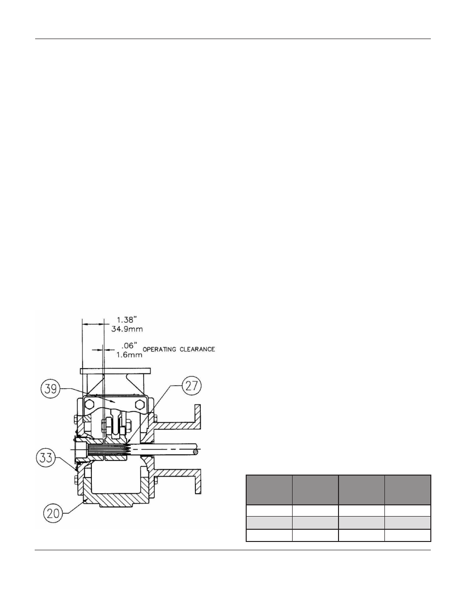
Figure 4: Lever Operating Clearance
Actuator
Size
Turnbuckle
(Key 16)
Lower
Locknut
(Key 14)
Upper
Locknut
(Key 18)
30
15/16
1/2
7/8
40
1-1/8
3/4
1-1/8
60
1-5/16
15/16
1-15/16
Table 2: Wrench Sizes Required for
Turnbuckle Adjustment, In
1051M S
erieS
r
otary
a
ctuator