Jordan Valve Mark HPX and HPAX Series Globe & Angle Style Панель управления User Manual
Page 6
-6-
25.
Increase the torque on each nut by an additional
1/4 of the torque value using the standard
crisscross pattern. Repeat this pattern
until the torque values in Table 4 have
been reached. Apply the final torque value
again and if any bolts turn, all of the bolts
will require retightening.
26.
Using the appropriate arrangement from Table
2, install new packing and metal packing box
parts. It may be necessary to pre-lubricate
packing parts with silicone-based grease.
27.
Using a smooth-edged pipe, cautiously tamp
each soft packing part into the packing
box. To prevent trapping air between the rings,
add one ring at a time without forcing them
below entrance chamber of the packing
box. With each additional ring the stack should
only be pushed down the thickness of one ring.
28. Install:
28.1. Packing Follower (key 14)
28.2. Wiper (key 13)
28.3. Packing Flange (key 3)
29.
Lubricate both the packing flange studs (key 1)
and the faces of the packing flange nuts (key 2).
Finger tighten the packing flange nuts.
30.
For packing type:
30.1. Spring-loaded PTFE V-Ring (Figure 2):
tighten the packing flange nuts
until there are no leaks.
30.2. Graphite: initially tighten the packing
flange nuts to the maximum torque
value in Table 3. Release the
packing flange nuts and retighten
them to the maximum torque value given
in Table 3.
30.3. Other packing types: tighten the pack
ing flange nuts in small increments alter-
nately. Repeat the process until
one of the nuts reaches the maximum
torque value from Table 5. Now
continue tightening the flange nuts
until the packing flange is level and at
right angles (90 degrees) to the
valve stem.
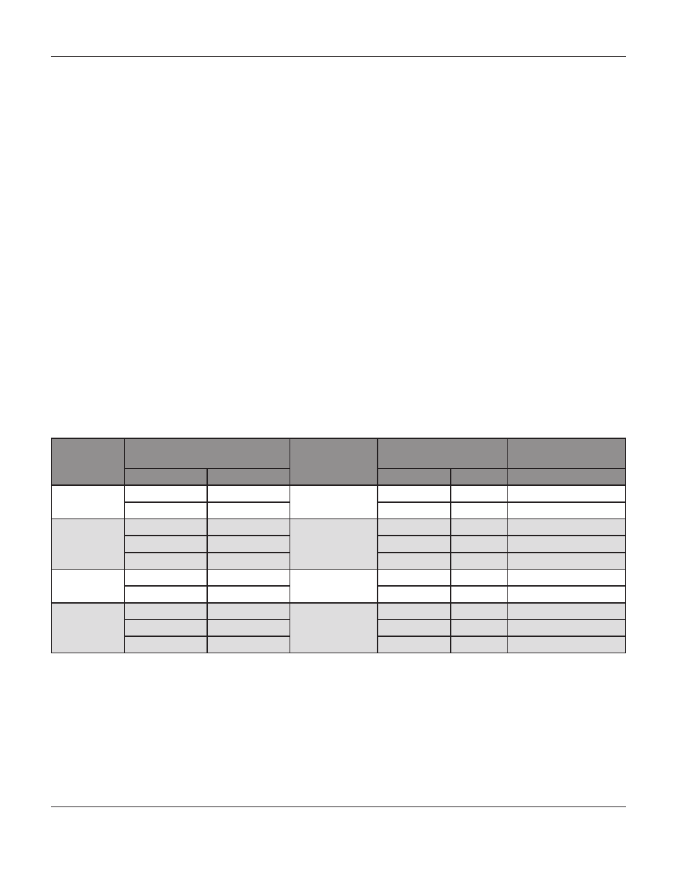
Table 4: Valve Stem Connection Torque and Drill Size for Groove Pin Hole
Valve Size,
Inches
Valve Stem Diameter
Valve Design
Valve Stem
Connection
Drill Size for Groove
Pin Inches
Inches
mm
Lbf•ft
N•m
2
1/2
12.7
HPX2D, HPAX2,
HPX5T, HPAX5
60-85
81-115
1/8
3/4
19.1
175-250
237-339
1/8
3
1/2
12.7
HPX2D,
HPX5T
60-85
81-115
1/8
3/4
19.1
175-250
237-339
3/16
1
25.4
310-355
420-481
1/4
4
3/4
19.1
HPX2D,
HPX5T
175-250
237-339
3/16
1
25.4
310-355
420-481
1/4
6
3/4
19.1
HPX2D,
HPX5T
175-250
237-339
3/16
1
25.4
310-355
420-481
1/4
1-1/4
31.8
610-670
827-908
1/4
Trim Removal
1.
Remove the actuator and the bonnet. Refer to
steps 1-4 in replacing packing.
2.
Remove the valve plug and stem assembly (key
20, 22). If the assembly is to be reused protect
the valve stem and plug seating surface
from nicks and scratches by taping them.
3. Remove:
3.1.
Cage (key 12)
3.2.
Bonnet Gasket (key 19)
3.3.
Seat Ring (key 23)
3.4.
Seat Ring Gasket (key 24)
4.
Follow the steps in the valve plug maintenance
procedure to complete the remaining steps for
rim removal.
M
ark
HPX
and
HPaX S
erieS
G
lobe
and
a
nGle
S
tyle
C
ontrol
V
alVeS