Jordan Valve Mark H-900 Series Globe Style Панель управления User Manual
Page 5
-5-
Trim Maintenance
Refer to this section for instructions regarding disas-
sembly, replacement of valve plug parts, grinding metal
seats and assembly of the valve body as required when
replacing trim.
During trim maintenance, always replace the gaskets
(Keys 4 and 5). With Mark ET trim, also replace the seal
ring (Key 6b).
Disassembly
1.
Complete steps 1 through 6 in the section titled
“Packing Replacement”.
2.
Lift out the cage (Key 12) and cage gaskets
(Key 5). If the cage is stuck, insert a
blunt tool into the groove around
the top of the cage and pry it free.
3.
Complete the required maintenance following
instructions in the sections “Replacing
Valve Plug Parts”, “Lapping Metal Seats”, or “As
sembly” as appropriate.
Replacing Valve Plug Parts
These instructions are for the TFE V-ring packing. Gra-
foil and Garlock packing is also available and is sup-
plied with complete replacement instructions.
Note: Do not use an old stem with a new valve
plug. Using an old stem would require drilling a new
groove pin hole, and doing so would weaken the
stem.
1.
To replace the valve plug stem (Key 3), begin
by driving out the groove pin (Key 10)
and removing the stem.
2.
Insert the new stem, threading it completely
into the valve plug (Key 11). Ensure that
all threads are engaged.
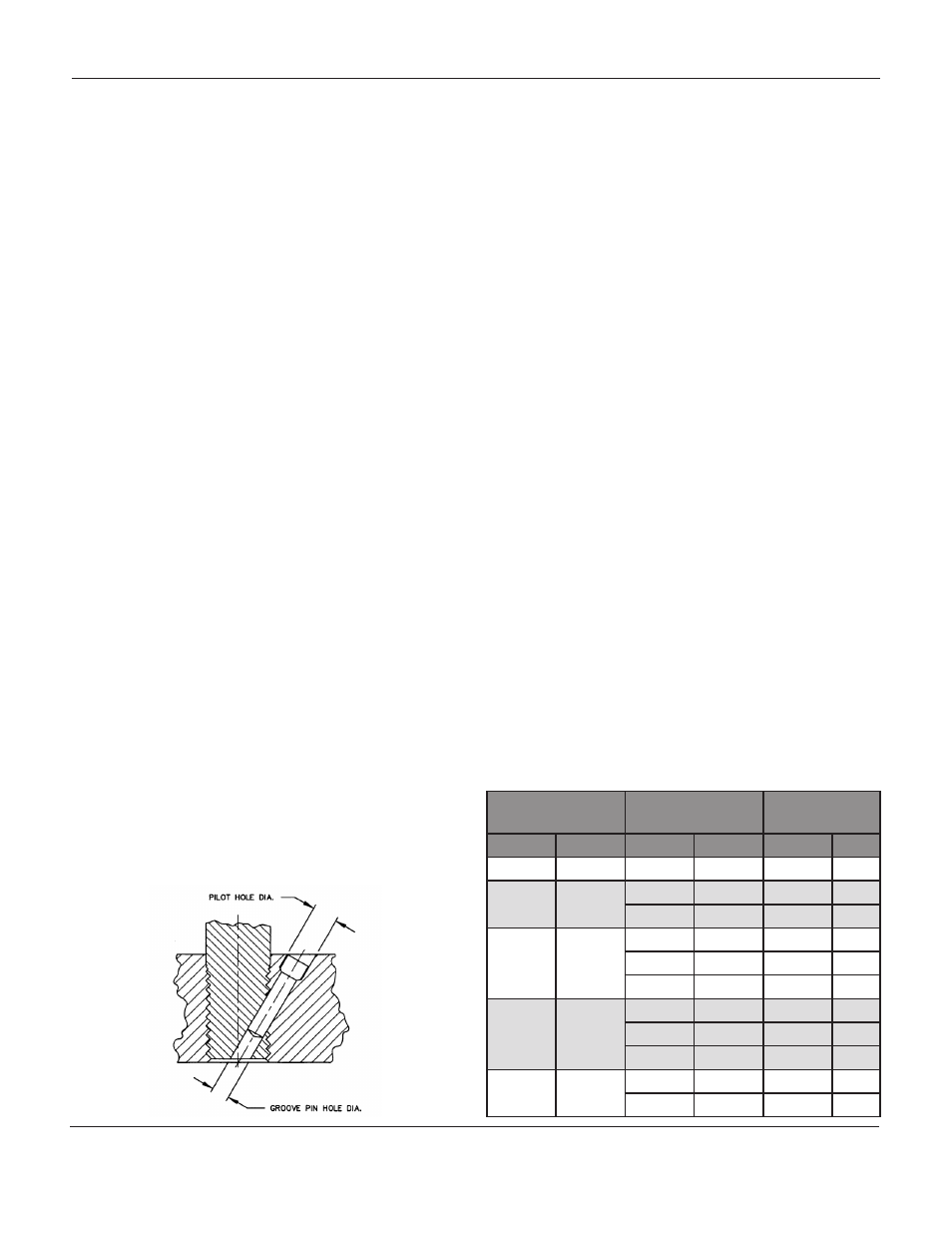
3.
Refer to Table 2 and drill the proper sized
groove pin hole through the stem. Insert the
groove pin which fastens the assembly togeth-
er.
4.
To replace the valve plug rings follow the in
structions appropriate for your trim configura-
tion:
4.1.
Mark ED Trim:
remove both piston
rings (Keys 6 and 6a) and replace them
if they show damage or uneven wear.
Install the rings while avoiding exces-
sive bending. Slip the ring with
a straight cut over the valve plug and
insert the ring into the groove. The ring
with the stepped cut slips over the
valve plug. Rotate the rings in
the groove until the two cuts are in op-
posite sides of the groove.
4.2.
Mark ET Trim:
Raise the end of the
retaining ring (Key 15) using a screw
driver. Rotate the plug and lift the ring
out and up. Avoid scratching any plug
or ring surfaces. Remove the metal
backup ring (Key 16) and TFE seal ring
(Key 6b). Refer to Figure 6 and install
the seal ring for
proper flow direction. Install the metal
backup ring. Insert one end of the
retaining ring (Key 15) into the groove
of the valve plug. While turning the
plug, press the ring into the groove,
being careful not to scratch the valve
plug and retaining ring.
5.
Continue with procedures for “Lapping Metal
Seats” or “Assembly” as required.
Table 2: Drill Size for Groove Pins
Port Size
Valve Stem
Connection
Drill Size
in
mm
in
mm
in
mm
1-5/16
33.3
1/2
12.7
3/32
2.4
1-7/8
47.6
1/2
12.7
1/8
3.2
3/4
19.1
1/8
3.2
2-5/16
58.7
1/2
12.7
1/8
3.2
3/4
19.1
3/16
4.8
1
25.4
3/16
4.8
2-7/8
73.0
1/2
12.7
1/8
3.2
3/4
19.1
3/16
4.8
1
25.4
1/4
6.4
3-7/16
87.3
3/4
19.1
3/16
4.8
1
25.4
1/4
6.4
M
ark
H-900, H-1500
and
H-2500 s
eries
G
lobe
s
tyle
C
ontrol
V
alVes