Aintenance – Jordan Valve Mark H-900 Series Globe Style Панель управления User Manual
Page 3
-3-
M
aIntenance
Internal valve components are subject to normal deterio-
ration and must be inspected and replaced as required.
The necessity of inspections and replacement of parts
will depend on the severity of service conditions. Inspec-
tions and maintenance must be carried out on a regular
basis.
Before beginning any maintenance, it is important to iso-
late the control valve and release all pressure contained
in the valve body and the actuator.
Packing Replacement
These instructions refer to the replacement of single or
double TFE V-Ring, Garlock and Grafoil packing. Key
numbers refer to Figures 1, 2 and 3.
1.
Release all loading pressure in the actuator and
remove control lines.
2.
Remove the cap screws from the stem
connecter and detach the halves of the stem
connecter.
3.
Unscrew the yoke locknut (Figure 3, Key 28) and
separate the actuator from the bonnet
(Figure 3, Key 17).
4.
Remove the hex nuts (Figure 1, Key 8) and lift
the bonnet (Figure 3, Key 17) and valve plug
and stem assembly from the valve body
(Figure 1, Key 7). Set those components on a
clean surface and protect the gasket sealing
serrations in the bottom of the bonnet. These
serrations are essential for a tight seal between
the body and bonnet during reassembly.
5.
Remove the bonnet gasket (Figure 1 and 2,
Key 4).
6.
Loosen the packing flange nuts (Figure 3, Key
20) so the packing becomes loose around the
stem.
7.
Remove the hex nuts from the valve plug stem
(Figure 1, Key 3) and pull the valve plug and
stem assembly out of the bonnet. Place
this assembly on a protective surface.
8.
Remove the hex nuts (Figure 3, Key 20), the
packing flange (Figure 3, Key 18), the packing
follower (Figure 3, Key 26) and the felt
wiper (Figure 3, Key 25).
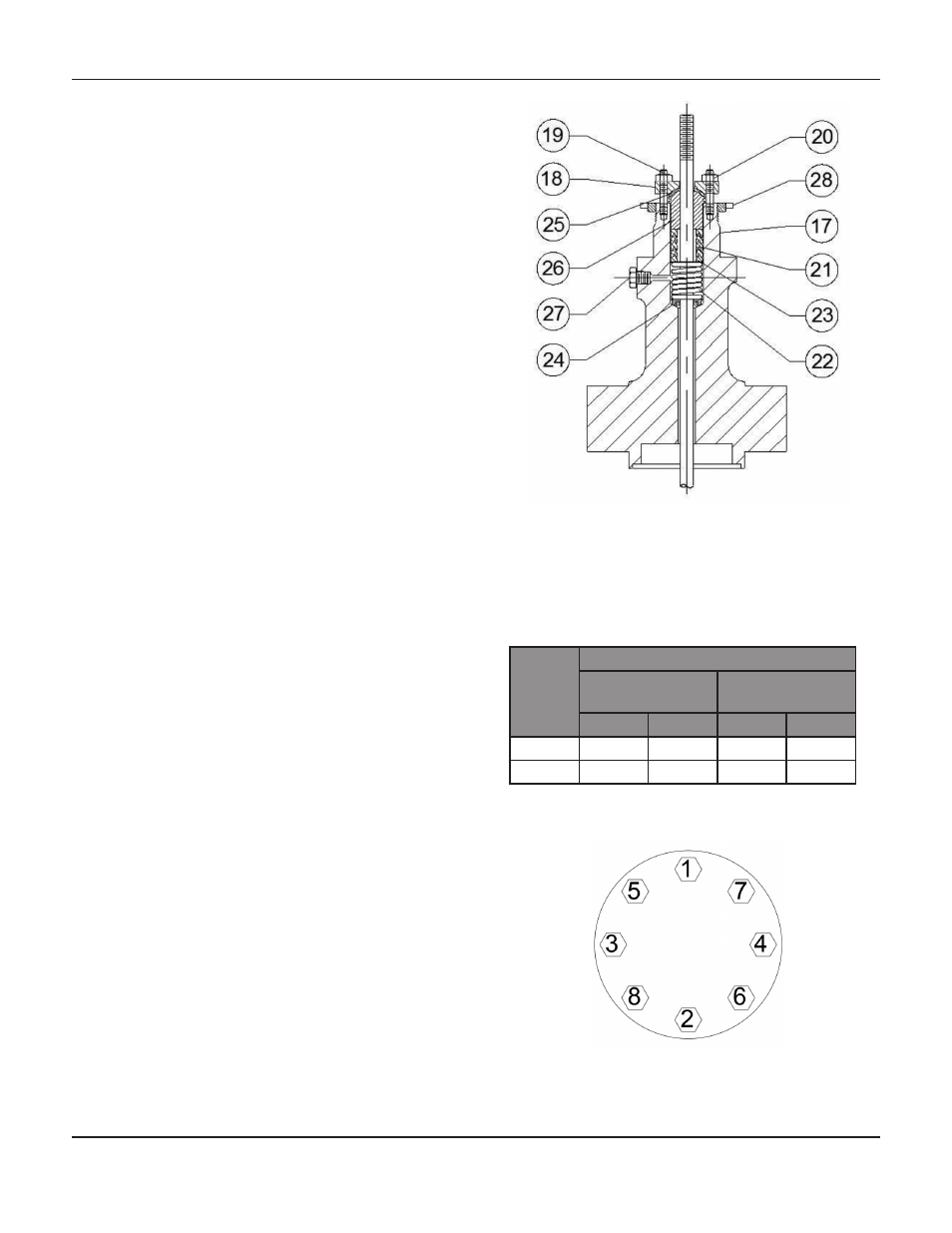
Figure 3: H-900, H-1500 and H-2500
Bonnet Parts
Table 1: Recommended Bonnet Bolt Torque
Body
Size
(in)
Bonnet Bolt Torque
Class H-900 &
H-1500
Class H-2500
Ft-lb
N-m
Ft-lb
N-m
3
404
548
404
548
4
540
732
540
732
Figure 4: Typical Bolting Pattern
s
eries
H-900, H-1500
and
H-2500 C
ontrol
V
alVes