Jordan Valve Mark H-900 Series Globe Style Панель управления User Manual
Page 4
-4-
Packing Replacement cont'd
9.
Use a packing hook to remove the packing
parts, or push them toward the top of the bon-
net using a small rod. Be careful not to scratch
the wall of the packing box.
10.
Clean the metal packing parts and the pack-
ing box, and check the valve stem and pack-
ing box surfaces for nicks or scratches.
Remove any light scratches with sanding. If
damage exists that cannot be sanded out, the
valve plug stem and bonnet must be replaced.
11.
Install a new bonnet gasket (Figures 2 and 3,
Key 4) onto the cage (Figures 2 and 3, Key
12).
Note: The valve plug assembly of the ED and ET fit
inside the cage with tight tolerances. When install-
ing the valve plug assembly be sure not to damage
the piston rings or the seal ring (Figures 2 and 3,
Keys 6, 6a, 6b).
When the bonnet is being mounted, the threads of
the valve plug stem will slide through the packing
box. If the packing has been installed, carefully at-
tach the bonnet to avoid cutting the packing on the
stem threads.
12.
Insert the valve plug assembly in the cage,
mounting the bonnet onto the body. Ensure
that the leak-off piping (or pipe plug, Figure 3,
Key 27) is facing downstream.
13.
Apply lubricant to the body stud bolts (Figures
1 and 2, Key 9) and the hex nuts (Figures 1
and 2, Key 8). Thread the nuts onto the body
stud bolts using good bolting practices. Refer
to Table 1 for proper bolt torques and tighten
the nuts in a criss-cross pattern (See Figure 4).
When the control valve assembly reaches
operating temperature, repeat the procedure.
Proper tightening of the bonnet nuts ensures
a positive sealing of the cage seals and the
spring seal.
Note: Repeating the bolting pattern may be neces-
sary since tightening one nut may loosen an adja-
cent nut. The body-to-bonnet seal will be complete
when none of the nuts will turn at the recommended
torque.
14.
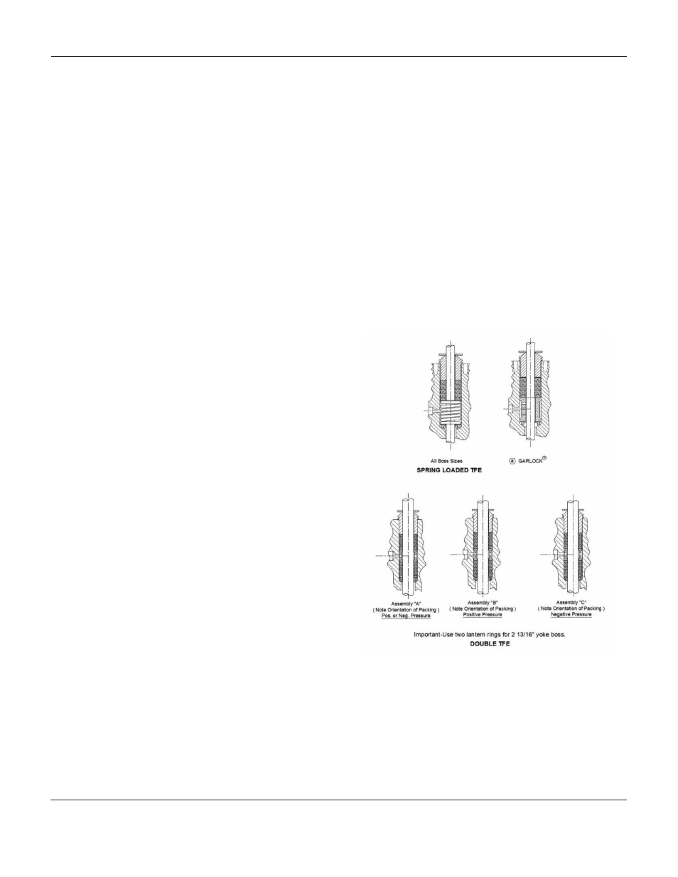
Refer to Figure 3 and arrange the packing
parts as outlined. Slide the new packing care
fully over the valve plug stem, and ensure that
the packing parts are not damaged by the
threads of the valve plug stem.
15.
Reinstall the packing flange and hex nuts
(Keys 18 and 20). Tighten the hex nuts until
the shoulder of the packing follower (Key 26) is
snug against the packing box.
16.
Mount the actuator onto the valve body assem-
bly and reconnect the actuator and valve stem
referring to procedures in the appropriate ac-
tuator manual.
Figure 5: Packing Arrangements
See Table 1 for Recommended Torque Values
GARLOCK is a registered trademark for packings, seals,
gaskets and other products of Garlock.
M
ark
H-900, H-1500
and
H-2500 s
eries
G
lobe
s
tyle
C
ontrol
V
alVes