Jordan Valve Mark DBAQ Series Angle Style Control Valve User Manual
Page 3
-3-
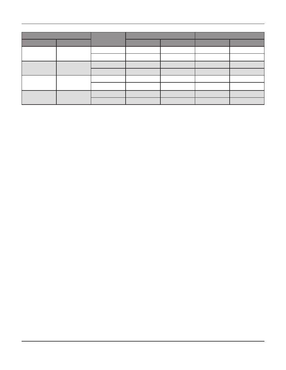
Stem Diameter
Valve Class
Rating
Lbf•Ft
N•M
Inch
mm
Min
Max
Min
Max
1/2
12.7
1500
11
16
15
22
2500
13
18
18
24
3/4
19.1
1500
25
37
34
50
2500
30
45
41
61
1
25.4
1500
38
57
52
77
2500
45
67
61
91
1-1/4
31.8
1500
50
75
68
102
2500
60
90
81
122
Table 1: Recommended Torque for Packing Flange Nuts
Adding Packing Rings
When using packing with lantern ring it may be possible
to add packing rings above the lantern ring as a
temporary measure without removing the actuator from
the valve body.
1.
Isolate the control valve from the line pressure
and release the pressure from the valve body.
2.
Remove the packing flange nuts (key 18, Figure
7) and lift the packing flange (key 16), upper
wiper (key 20) and packing follower (key
21, Figure 7) away from the valve body.
3.
Take care when removing out the old packing
rings to avoid scratching the valve plug
stem or packing wall. Clean all
metal parts to remove debris that
would prevent the packing from sealing properly.
4.
Should split ring packing be added, spread the
rings over the stem and slide the rings into
the packing box. Alternate the position
of the splits to avoid creating a leak
path. If solid ring packing is being
added, remove the stem connector and
slip the rings over the end of the valve stem.
5.
Re-assemble the packing follower, upper wiper,
packing flange, and packing flange nuts. (keys
21, 20, 16, and 18).
6.
Reconnect the body actuator stem connection
according to the appropriate manual. Torque
accordingly, reference Table 3.
Replacing Packing
Prior to beginning any maintenance, it is important to
isolate the valve from the line pressure, and to release
all pressure from the valve body. Disconnect all operat-
ing lines to the actuator, including air pressure, electri-
cal power or control signal lines. The process pressure
should be released both upstream and downstream of
the valve. Drain the process fluid from both sides of the
valve.
Employ lockout procedures to ensure the safety of per-
sonnel and equipment during the valve service.
NOTE: Extreme caution must be used during the dis-
assembly. Nicks and scratches will affect the ability
to seal the valve in the future.
1.
Remove the capscrews in the stem connector
and separate the two halves. Exhaust all actua-
tor pressure if any was applied, and discon-
nect the actuator supply and leak off piping.
2.
Remove the yoke locknut, and remove the
actuator from the bonnet (key 2).
3.
Loosen the packing flange nuts (key 18), and
remove any travel indicator parts and stem
locknuts from the valve stem threads
M
ark
DBaQ S
erieS
a
ngle
S
tyle
C
ontrol
V
alVeS