Yaskawa SmartTrac CPU Card User Manual
Page 10
SMART TRAC CPU Card
6
••
Installing the Smart Trac CPU Card Technical Manual
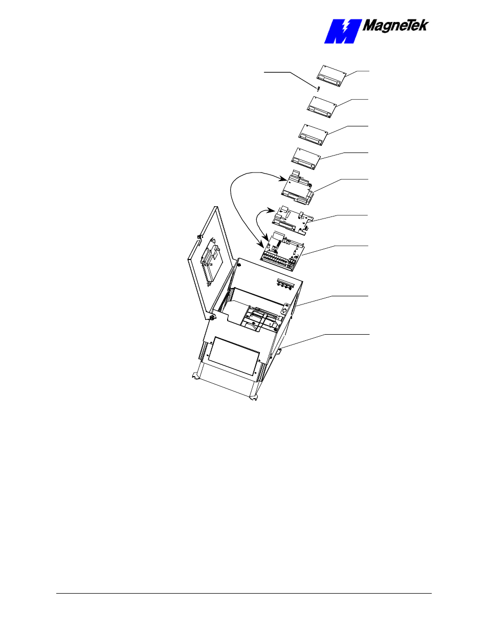
2CN
Connector
4CN
Connector
PG Card
PS Card
Ethernet
Card
Adapter
Ring
Card
PC/104
Optional
Card
PC/104
Optional
Smart Trac
Smart Trac
Smart Trac
Smart Trac
CPU Card
Card
Inverter Control
Main Chassis
Standoffs (4
places on top of
each card)
Figure 1. Smart Trac CPU Card Stack Position.
1. Install the Smart Trac CPU card. Align the male PC/104 connector pins
on the Smart Trac CPU card with the female PC/104 connector on the
Inverter and the standoff holes with metal standoffs on the Inverter.
When in place, gently but firmly push the Smart Trac CPU card in
place on the Inverter card.
2. Orient the PG card so that the PC/104 connector and the J2 connector
align with the PC/104 connector on the Smart Trac CPU card and the
4CN connector on the Inverter Control board. Be careful to align the
PC/104 connector pins with the receptacle on the Smart Trac CPU card
so the pins don’t bend when the card is pushed into place.
3. Gently but firmly push the Smart Trac PG card onto the Smart Trac
CPU card. Make sure connecting pins are in alignment and J2 mates
with 4CN before pushing the two boards tightly together. Secure the
card using four (4) metal standoffs and one (1) plastic standoff.