Yaskawa PLC-5 User Manual
Page 26
TROUBLESHOOTING
23
TROUBLESHOOTING – SmartMUX Board
12/22/94- RD 3196-10
TROUBLE-
SHOOTING –
SmartMUX
Board
TROUBLE-
SHOOTING –
A-B PLC-5 or
PLC-3
Esure that the PLC I/O status screen does not indicate this rack is inhibited.
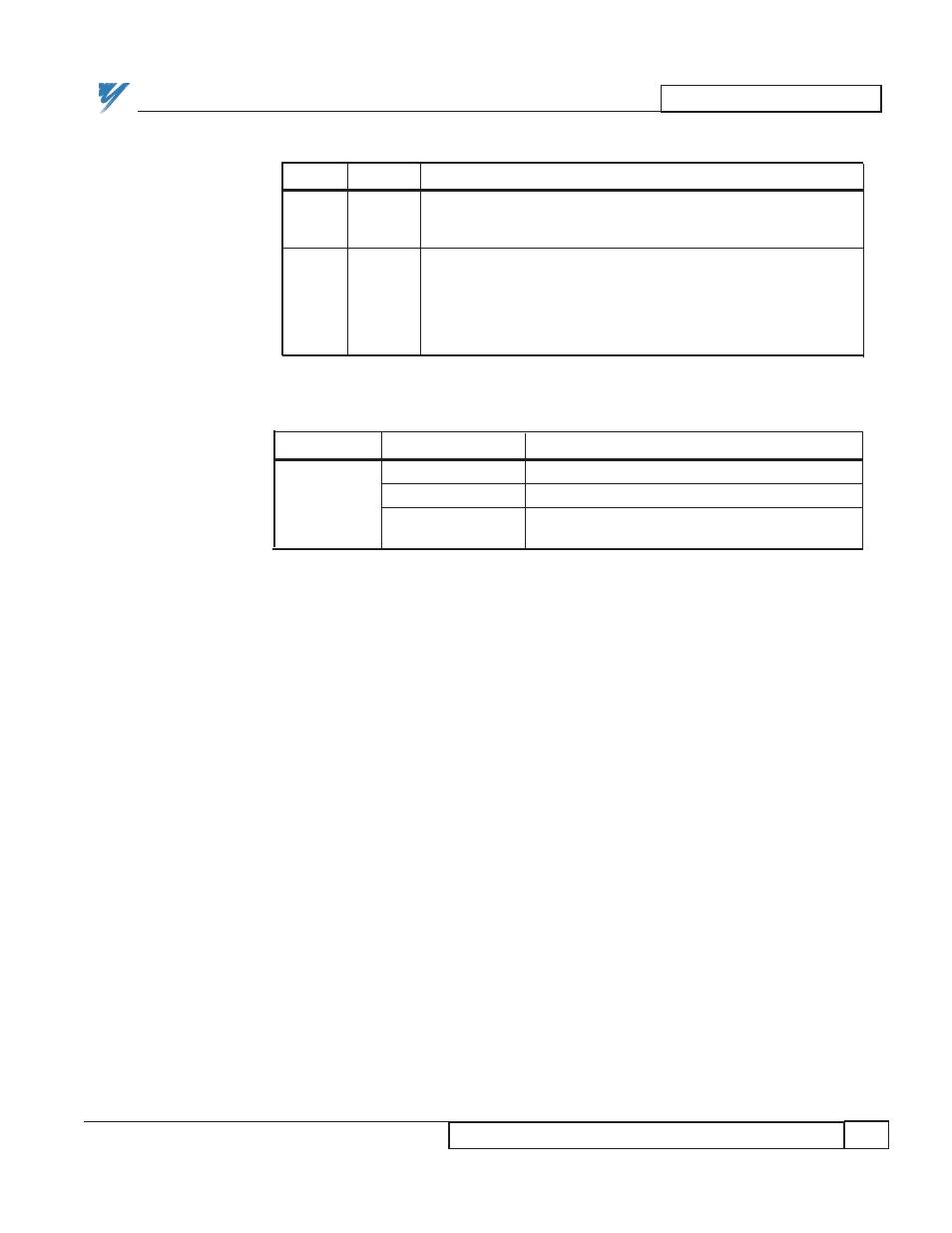
Table 13. Troubleshooting the SmartMUX Board
LED
COLOR
DESCRIPTION
STATUS
RED
When the SmartMUX board has proper +5V power from the
(PWR)
power supply, this LED will flash once if the node is an odd
rack address or twice if the node is an even rack address.
COMM
GREEN
When the Allen-Bradley PLC establishes communication with
(LED1)
the SmartMUX board, this LED will flash or be ON. A flashing
COMM LED means the PLC is in program mode. A solid or
ON COMM LED means the PLC is in run mode and
information is being transferred. During proper operation with
the PLC in run mode, this LED is ON.
Table 14. Troubleshooting the PLC
LED
COLOR
DESCRIPTION
GREEN STEADY
Communication is OK.
Remote I/O
RED STEADY
No Communication.
GREEN/RED BLINK
Communication OK with some remote racks,
but not with all specified racks.