Terminating the remote i/o link – Yaskawa PLC-5 User Manual
Page 12
HARDWARE
9
Terminating the Remote I/O Link
12/22/94- RD 3196-10
MagneTek Part
Description
Number
05P00090-0327
AC Output Module
05P00090-0328
AC/DC Input Module
05P00090-0329
DC Output Module
05P00090-0330
DC Input Module
05P00090-0331
SPST Relay Output Module
The SmartMUX board is an Allen-Bradley Pyramid Solution product.
Therefore, it must meet Allen-Bradley wiring and communication
specifications. Terminating the remote I/O link is part of the specification the
SmartMUX board must meet. A user must place a terminating resistor on both
physical ends of a remote I/O link to ensure proper operation.
NOTE: Refer to Allen Bradley’s 1785 PLC-5 Family Programmable
Controllers, Hardware Installation Manual, Publication 1785-6.6.6
June 1993 or later, page 7-10 for proper terminating resistor
installation instructions.
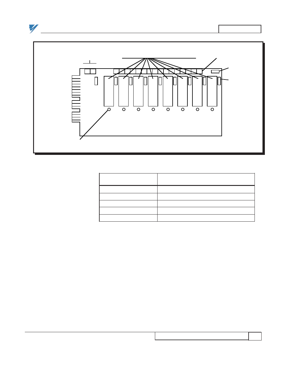
Figure 3. Local I/O Interface Board
Figure 3a. Local I/O Interface "Plug-In" Modules
8 LEDs (0 - 7)
+ –
1A Fuse
0
1
2
3
4
5
6
7
1
16
Fuse
5A
Spare
5A Fuse
Terminals
Terminals
for power
Input or Output (AC or DC) modules
SmartMUX
Edge
Connector
Terminating the
Remote I/O Link