General operation, Sample plc ladder diagram, Figure 10. sample plc ladder diagram – Yaskawa PLC-5 User Manual
Page 22
GENERAL OPERATION
19
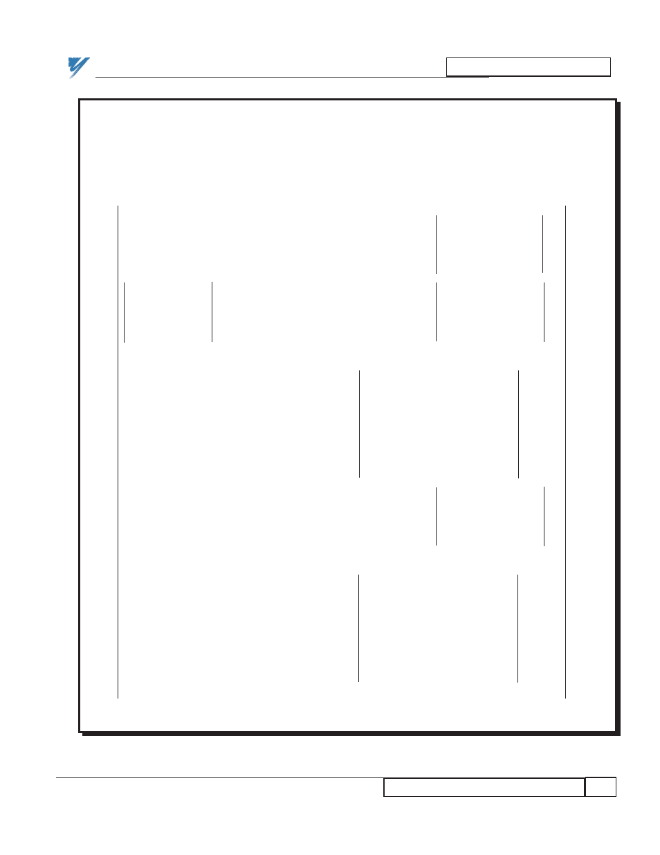
Sample PLC Ladder Diagram
5/2/95- RD 3196-10
Figure 10. Sample PLC Ladder Diagram
ABBREVIATION KEY
DSD_INT = Drive network interface to the PLC.
DSDTOPLC = Data transferred from the drive to the PLC.
DSDTOPLC_OLD = Temporary storage of DSDTOPLC for detection of changes in value.
LOAD_PLC = True indicates the value stored in the PLC is to be transferred to the drive.
PLC_DATA = Data to be moved into the PLCTODSD register when the LOAD_PLC bit is true.
PLCTODSD = Data transferred from the PLC to the Drive.
LOAD_PLC
—MOV—————————
0 ——| |—————————————————————————————–———— Move
— —–
Source:
PLC_DATA
0
Dest:
PLCTODSD
0
————————————
—NEQ——————–
—MOV—————————
1 – Not Equal (A<>B) —————————————————————————– Move
— —–
A: DSDTOPLC
Source:
DSDTOPLC
0
0
B: DSDTOPLC_OLD
Dest:
PLCTODSD
0
0
—————————–-
———————————–-
Data Moves to
DSD_INT
CW
C_W
—BTW———————————————
2 ——————| / |———————– | / |——————————–- .Block Transfer Write
–—(EN)—–
EN
EN
Mod Type:
1771-??
Other BLK XFER Module –—(DN)
Rack:
2
Group:
0 –—(ER )
Module:
0
Control Block: CONTROLWORD
Data File:
PLCTODSD
Length:
64
Continuous:
N
——————————————————–
—MOV————————–
3 ————————————————————————————————————– Move
— —–
Source: DSDTOPLC
0
Dest: DSDTOPLC_OLD
0
————————————
Data Reads from
DSD_INT
C_W
CW
—BTR———————————————
4 ——————| / |———————– | / |——————————–- Block Transfer Read
–—(EN)—–
EN
EN
Mod Type:
1771-??
Other BLK XFER Module –—(DN)
Rack:
2
Group:
0 –—(ER )
Module:
0
Control Block: CONTROL_WORD
Data File:
DSDTOPLC
Length:
64
Continuous:
N
——————————————————–
5 ———————————————————————————–————————————————————-(END)—