Trouble- shooting – jarc board – Yaskawa PLC-5 User Manual
Page 25
TROUBLESHOOTING
22
TROUBLESHOOTING – JARC Board
12/22/94- RD 3196-10
TROUBLE-
SHOOTING –
JARC Board
If the hand held PCDU terminal does not operate properly after plugging into
the JARC board J3 RS-232 connector, unplug it and try again. If it still does
not show any display, then check the F1 fuse on the JARC board. This fuse
protects the +5V power to the PCDU terminal.
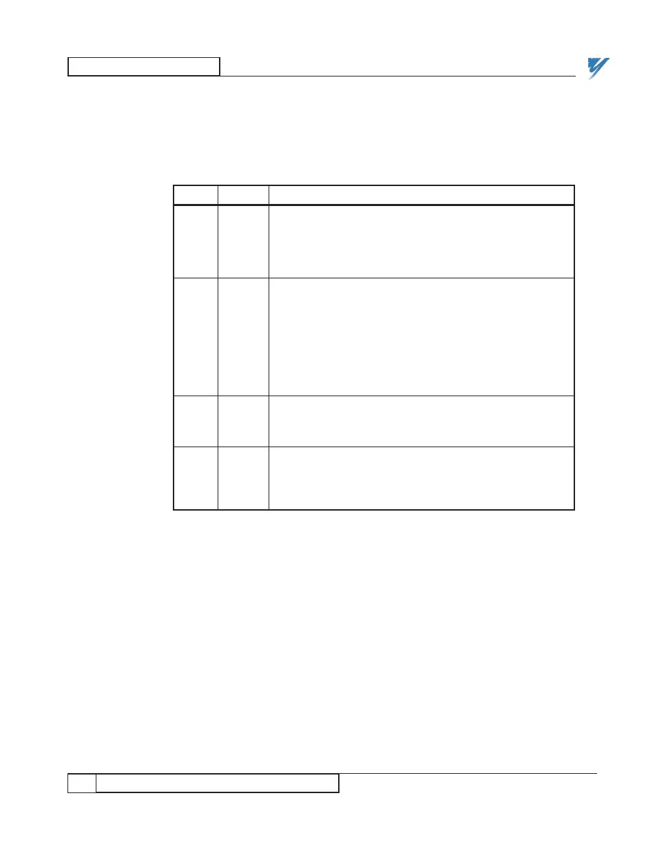
Table 12. Troubleshooting the JARC Board
LED
COLOR
DESCRIPTION
PWR
RED
When the JARC board has proper +5V power from the power
(D1)
supply, this LED will turn ON and remain ON. If the LED is
OFF, then the power supply is bad, or the connection between
the power supply and the JARC board is bad. The four
position Phoenix connector, J7, is used to connect the ±5V,
common and GND.
RECON YELLOW
The yellow RECON LED is used for displaying the occurrence
(D3)
of a network reconfiguration. A reconfiguration occurs when-
ever a new node enters the network. During power-up, start-
up, or initialization of any node on the network this LED will
turn ON for approximately 1 second and then turn OFF. If
several nodes are powering up at the same time, then the LED
may be on for 2-5 seconds. In the normal operating state, the
RECON LED must be off. If the RECON LED is always ON,
then the JARC board is the only node on the network, or one
of the other nodes has a network interface hardware problem.
XMIT
RED
The XMIT LED is used to show that the JARC board is
(D4)
enabled to transmit on the network and that the board is
transmitting network tokens. The XMIT LED should be ON
during normal operation.
PGM
RED
The PGM LED is used to display errors during initialization.
(D2)
The normal state of this LED is OFF. If this LED is ON, first
reapply power to the JARC board by powering down and then
powering up. If the LED remains ON, a hardware problem with
the JARC board has been detected and service is required.