Yaskawa F7 Drive Overvoltage Suppression User Manual
Page 7
Date: 09/17/2010, Rev: 09-2010
Page 7 of 9
TM.F7SW.062
5.2 Open Loop Vector Control
In order to obtain optimal performance when using the Open Loop Vector control method (A1-02 = 2), a
motor auto-tune should be performed. Ideally, the motor should be uncoupled from the load, and a
Rotational auto-tune (T1-01 = 0) should be performed.
If the motor cannot be uncoupled from the load, then a Stationary auto-tune (T1-01 = 1) should be
performed. In the this software, Motor Rated Slip and Motor No-Load Current are not calculated in the
Stationary auto-tuning method. Therefore, these need to be calculated and manually entered prior to
running the Stationary auto-tune. After entering the E2-02 and E2-03 values, perform the auto-tune.
Motor Rated Slip (E2-02) should be calculated as follows:
Example: 4-pole, 60 Hz motor, Motor Rated Speed = 1730 RPM
E2-02 = (Motor Synchronous Speed - Motor Rated Speed) * Motor Poles / 120
E2-02 = (1800RPM - 1730RPM) * 4 / 120
E2-02 = 2.33 Hz
Motor No-Load Current (E2-03) can sometimes be read directly off of the motor nameplate; it is often listed
as NLA (no-load amps). If there is no listing on the nameplate, motor no-load current can be estimated as
follows: Motor full load current (FLA) * 35%.
Example: 4-pole, 60 Hz motor, Motor FLA = 60 Amps.
E2-03 = 60 Amps * 35%
E2-03 = 21 Amps.
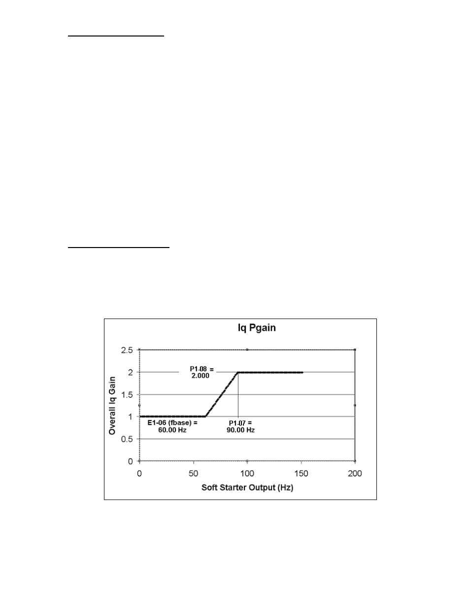
5.3 OV Regulator Gain Increase
Parameters P1-07 (OV Regulator Gain Frequency) and P1-08 (OV Regulator Gain Multiplier) automatically
increase the overvoltage suppression regulator gain (P1-02) when the drive’s output is above the motor
base frequency (E1-06). This is sometimes necessary to compensate for the motor’s reduced torque
characteristics above its base speed (otherwise known as the constant horsepower or field weakening
area). Shown below is an example when E1-04 = 150Hz, E1-06 = 60Hz, P1-02 = 1.00, P1-07 = 90.00 Hz,
and P1-08 = 2.000.
Figure 2: OV Regulator Gain Multiplier Above Motor Base Speed