Yaskawa F7 Drive Overvoltage Suppression User Manual
Page 2
Date: 09/17/2010, Rev: 09-2010
Page 2 of 9
TM.F7SW.062
This document is intended to provide proper installation and use of the Yaskawa drive with custom software. This
document is a supplement to the standard drive technical manual. It describes the effects on the drive parameters
and functions with the software installed. Read and understand this document and the standard drive technical
manuals before attempting to install, adjust, operate, inspect or maintain the drive. Observe all cautions and
warnings in this document and the standard drive technical manuals. Custom software is written to add
functionality to a standard AC drive to enhance or enable use in a specific application. The software is loaded to
the flash ROM area of the control board, and replaces the standard drive software. Custom software can add new
functions, modify standard functions, or even inhibit standard functions. It can be used to modify display text or
parameter names. Custom software is usually loaded to the drive before delivery. The control board and drive
nameplate are assigned unique part numbers and the software is registered, archived, and retrievable.
When seeking support for a drive with custom software, it is imperative to provide the unique part number shown
on the drive nameplate. The software has been flashed to the control board memory and the operation of
parameters, functions, and monitors are different than the standard drive software, as described herein.
1.0 Overview
This Overvoltage Suppression software allows an F7 drive to control rotating machinery where part of the
machine’s cycle creates a cyclic regenerative (over-hauling) load. The Pump Jack Oil Well and
Stamping/Punch Press are two applications that this software was specifically created for. The benefit of this
software it that dynamic braking resistors are not required for normal operation.
This software monitors the torque-producing current (Iq) in the motor, and regulates this against an Iq setpoint
using a PI controller. If the torque producing current falls below the setpoint, the output frequency is increased
to force a higher (positive) Iq and thus avoid a regenerative condition in the motor.
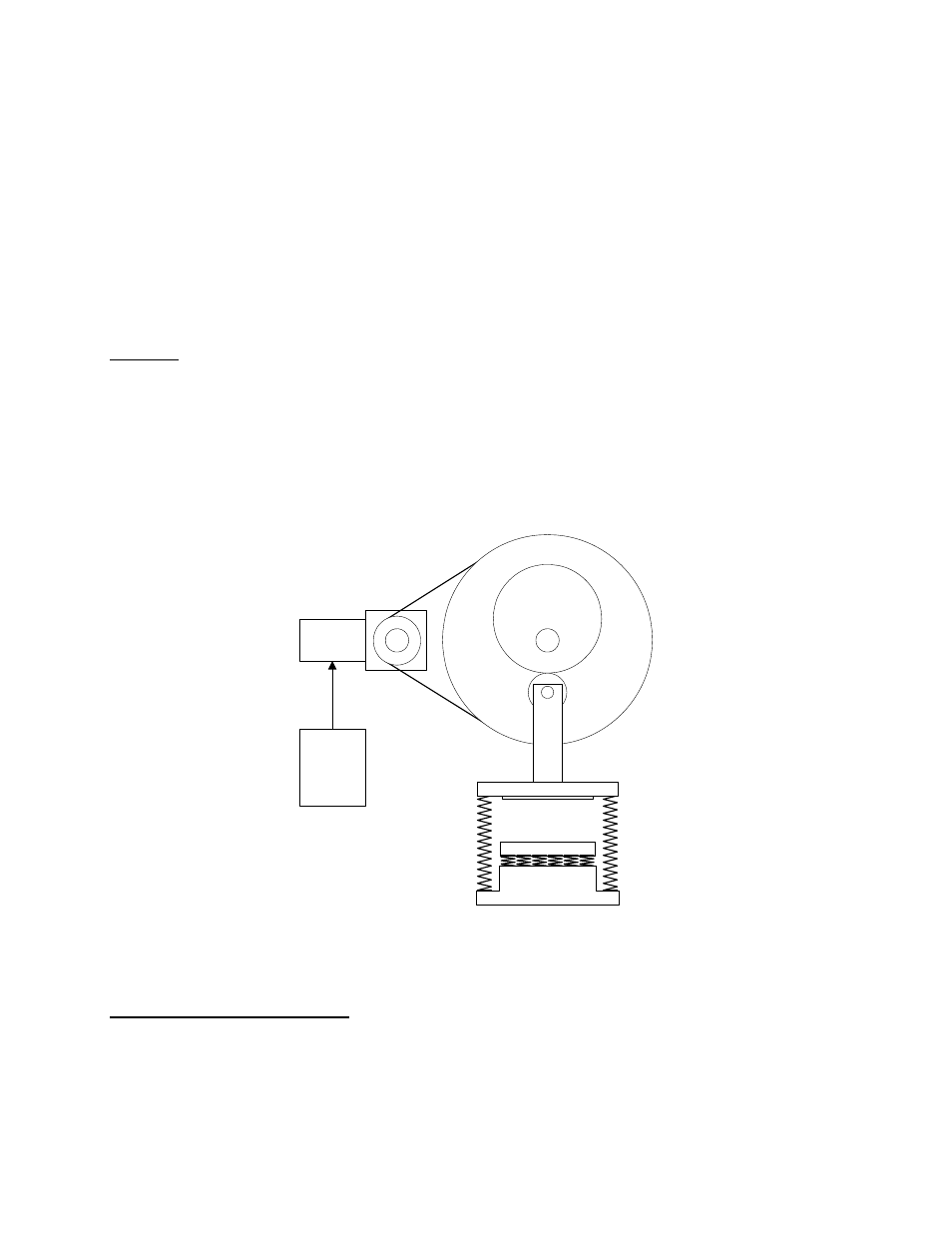
Stamping Press Application
2.0 Changes from Standard Product
a. The “Ramp to Stop” stopping method (B1-03 = 0) is deleted.
b. Several parameter defaults have changed. See section 4.5.
c. The Stationary auto-tuning method (T1-01 = 1) will not set E2-02 (Rated Slip) and E2-03 (No-load
Current). Therefore, these parameters must be manually set using the motor’s nameplate data. See
Section 5.2.
Motor /
Gear Box
F7
Flywheel
Clutched
Cam