A1000, 5 installation procedure, Connection diagram – Yaskawa MECHATROLINK-III User Manual
Page 22
5 Installation Procedure
22
YASKAWA ELECTRIC TOBP C730600 62B 1000-Series Option SI-ET3 Installation Manual
6.
Connect the MECHATROLINK-III communication cable to option communication
connector CN1 or CN2. Refer to
Communication Cable Wiring on page 23
details.
Install MECHATROLINK-III communications cables apart from main-circuit wiring
and other electrical and power lines. Ensure the cable end is firmly connected (see
).
Note: Maximum transmission distance is 100 m (3937.0 in.). Minimum wiring distance between
stations is 0.2 m (7.9 in.).
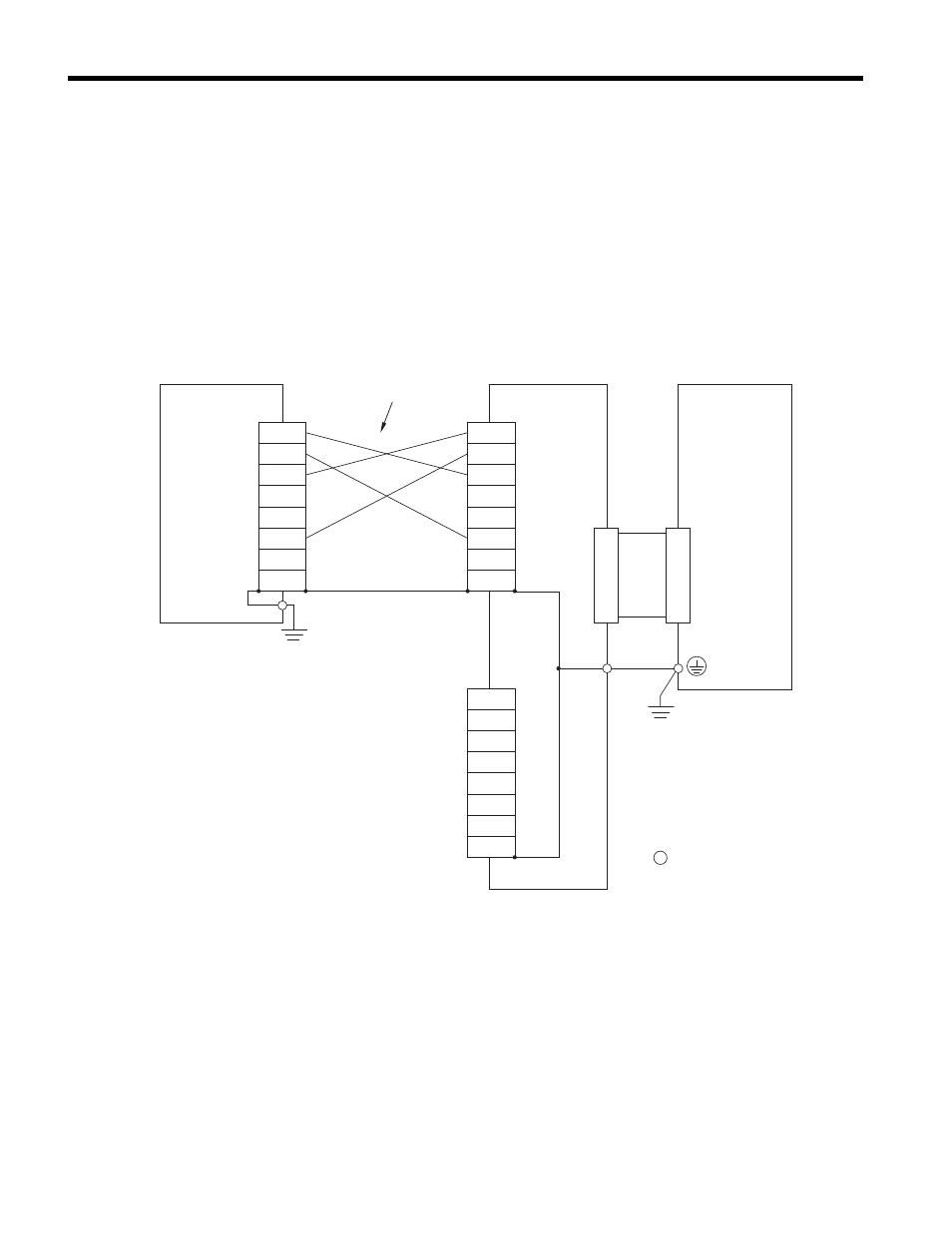
Connection Diagram
Figure 8 Option Connection Diagram
<1> Use connector CN1 or CN2 to connect with the MECHATROLINK-III master. Refer to
for details.
A1000
TXD_P
TXD_N
RXD_P
NC
NC
RXD_N
NC
NC
TXD_P
TXD_N
RXD_P
NC
NC
RXD_N
NC
NC
MECHATROLINK-III
Master
SI-ET3
CN2
<1>
TXD_P
TXD_N
RXD_P
NC
NC
RXD_N
NC
NC
CN1
<1>
FE
Drive
control circuit terminal
MECHATROLINK-III
Communication Cable