SMA SB 1300TL Service Manual User Manual
Page 18
3. If a definite ground fault cannot be measured and the message is still displayed, measure the
insulation resistance.
4. Reconnect the strings without ground faults to the inverter and recommission the inverter (see
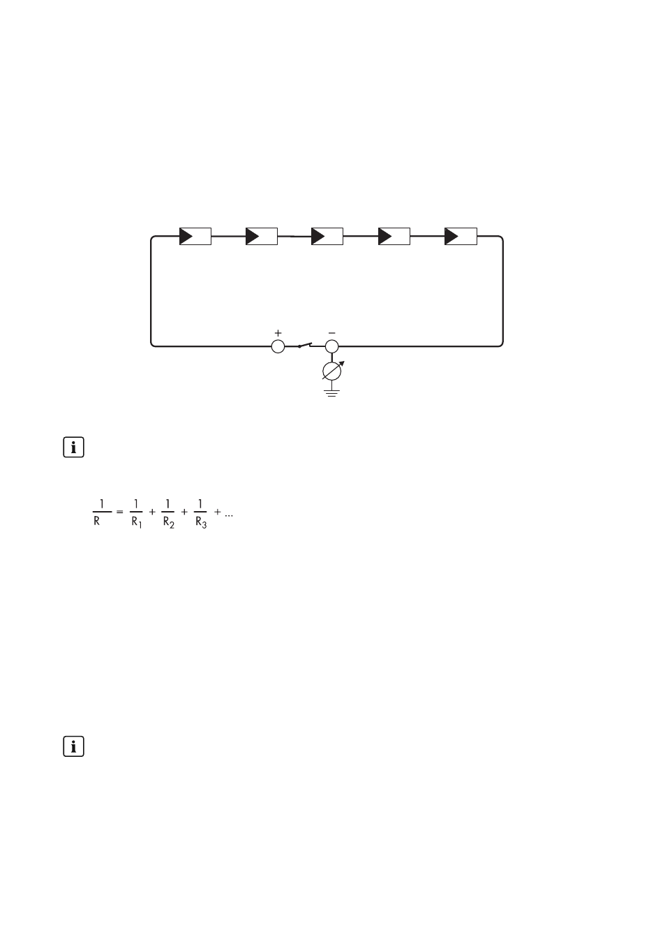
Test by Measuring the Insulation Resistance
If the voltage measurement does not accurately indicate a ground fault, the insulation resistance
measurement can provide more detailed results.
Figure 1: Schematic diagram of the measurement
Calculating the insulation resistance
The expected total resistance of the PV system or of an individual string can be calculated
using the following formula:
total
The exact insulation resistance of a PV module can be obtained from the module manufacturer
or the datasheet.
For the resistance of a PV module an average value can be assumed: for thin-film PV modules
approximately 40 MOhm and for polycrystalline and monocrystalline PV modules
approximately 50 MOhm per PV module (for further information on calculating the insulation
resistance see the Technical Information "Insulation Resistance (Riso) of Non-Galvanically
Isolated PV Systems" at ).
Required devices:
☐ Suitable device for safe disconnection and short-circuiting
☐ Measuring device for insulation resistance
Device required for safe disconnection and short-circuiting of the PV array
The insulation resistance can only be measured with a suitable device for safe disconnection
and short-circuiting of the PV array. If no suitable device is available, the insulation
measurement must not be carried out.
4 Troubleshooting
SMA Solar Technology AG
Service Manual
SB13-21TL-SG-en-11
18