SMA BEAM REPEATER User Manual
Page 10
Determining the Installation Location
SMA Solar Technology AG
10
SBeamRep-BEN091911
User Manual
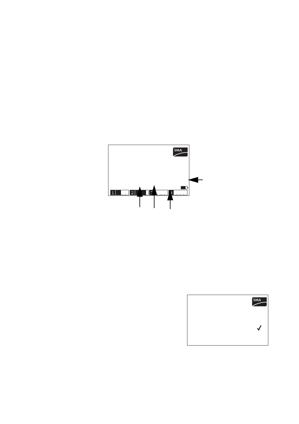
6. Here, you can read the communication quality (see figure below) which is calculated on the
basis of the ratio between the lost data packets and the sent data packets.
The registered inverters are listed with the last five digits of the serial number. The following values are
also specified:
"S"= data packets sent
"LS"= data packets lost on sending
"LR" = data packets lost on receipt
This is followed by the communication quality calculated in %.
The communication quality specifies the ratio between received and sent data packets of the
registered inverters. With a communication quality of 100 %, the signal strength is very good and no
data packets are lost.
7. Move away with the Sunny Beam towards the desired installation location until the first data
packets are shown to be lost under LS or LR. Then move back towards the inverters again until
no more data packets are being lost.
8. Install the Sunny Beam Repeater at this location. First connect the provided USB power supply
to the Sunny Beam Repeater, then plug the power plug into a socket.
The Sunny Beam Repeater starts up.
All LEDs on the Sunny Beam Repeater briefly shine green. The Sunny Beam Repeater starts up.
This procedure takes approximately 1 minute.
9. In the Sunny Beam main menu, select "SETUP/PLANT"
and set a check mark beside the menu item
"REPEATER".
10. Select "EXIT" repeatedly until the prompt window
opens.
11. Select "Yes" in the prompt window. The setting is saved.
3.PB V:0.00 4.PB V:0.00
SBeam V2.21EU firmware
DIAGNOSTICS
1.PB V:2.10 2.PB V:2.04
DEVICE S LS LR
.67890: 204 0 0 100%
3.07V
.67891: 204 0 0 100%
S
LS
LR
Communication quality in %
PLANT
Sunny Boy DETECTION
EXCLUDE Sunny Boys
GROUP
REPEATER :
EXIT