SMA DU-SC-US User Manual
Page 31
SMA America, LLC
Preparing the Disconnect Unit for Installation
Unpacking
DISU_SCUS-AP-eng-IUS110911
31
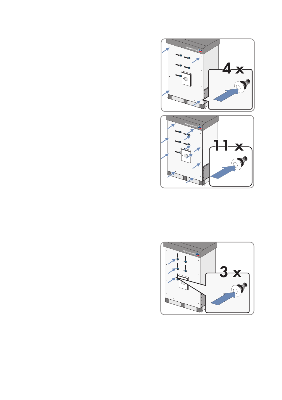
5. Fit the front plate of the enclosure to the Disconnect
Unit with four screws and four sealing washers at its
four corners. Tighten the screws so that they are hand-
tight (the front plate of the enclosure can still be
moved).
6. 11 accessible holes are left without screws on the
front plate. The three holes behind the left handles
are not reachable yet. Insert one screw with sealing
washer in each of the 11 holes. Fasten the screws
hand-tight.
7. Ensure that the front plate of the enclosure is aligned at the edges of the Disconnect Unit. Tighten
all screws with a torque of 44 in-lbs. (5 Nm).
8. Ensure that all switches are functioning correctly. Switch all switches into the "On" position and
then back into the "Off" position.
The switches function properly if there is no clearance of the shafts and the switches make a
clear switching noise. Readjust if necessary.
9. When all switches are functioning correctly: Switch
all switches into the "On" position and insert three
screws with sealing washers into the holes on the
handles on the left-hand side. Tighten screws with a
torque of 44 in-lbs. (5 Nm).
10. Switch all switches into the "Off" position.