SMA String-Monitors Alarm Contact Kit User Manual
Page 19
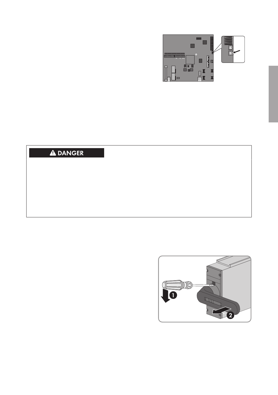
14. On the electronic assembly, push the cable plug
onto the pin header X6.
1 2 3 4 5 6 7 8
9
1112
14
15. Remount the protective covers in the SMA String-Monitor (see SMA String-Monitor manual).
16. Replace the rotary handle horizontally (position 0, OFF, green area) onto the square bolt. The
rotary handle snaps into place with an audible click.
17. Switch the SMA String-Monitor back on (see SMA String-Monitor manual).
6 Uninstalling the Alarm Contact for the DC Load-Break
Switch
Danger to life from electric shock due to live voltage
High voltages are present in the live components of the DC sub-distribution. Touching live
components results in death or serious injury due to electric shock.
• Disconnect the inverter on the DC side (see the inverter manual).
• Disconnect the DC sub-distribution (see the DC sub-distribution manual).
• Disconnect all DC sub-distributions that are connected in parallel in the DC connection area
(see the manual of the respective DC sub-distribution).
Procedure:
1. Disconnect the inverter on the DC side (see inverter manual).
2. Disconnect the SMA String-Monitor (see SMA String Monitor manual). Do not attach a lock on
the rotary handle of the DC load-break switch.
3. Use a screwdriver to lever up the catch
mechanism above the rotary handle, and pull
the rotary handle forwards and off.
4. Disassemble the protective covers in the SMA String-Monitor (see SMA String-Monitor
manual).
5. Remove the cover of the DC load-break switch to which the rotary handle was attached.
• Release the screws of the cover with a cross-head screwdriver (PZ1).
• Remove the cover.
6 Uninstalling the Alarm Contact for the DC Load-Break Switch
SMA Solar Technology AG
Installation Manual
19
MeldeLasttr-IA-xx-10
ENGLISH