4 mounting position and cable route, Mounting position and cable route, Installing alarm contact for dc load-break switch – SMA String-Monitors Alarm Contact Kit User Manual
Page 16
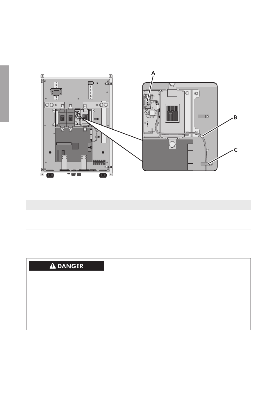
4 Mounting Position and Cable Route
The figure illustrates the mounting position and cable route in an SMA String-Monitor of device type
SSM-U-XX15. The mounting position and cable route is analogous for the SMA String-Monitor of
device type SSM-U-XX10.
Figure 4 : Mounting position of the alarm contact and cable route in the SMA String-Monitor SSM-U-XX15
(example)
Position
Explanation
A
Mounting position of the alarm contact in the DC load-break switch
B
Cable route
C
Cable lug
5 Installing Alarm Contact for DC Load-Break Switch
Danger to life from electric shock due to live voltage
High voltages are present in the live components of the DC sub-distribution. Touching live
components results in death or serious injury due to electric shock.
• Disconnect the inverter on the DC side (see the inverter manual).
• Disconnect the DC sub-distribution (see the DC sub-distribution manual).
• Disconnect all DC sub-distributions that are connected in parallel in the DC connection area
(see the manual of the respective DC sub-distribution).
4 Mounting Position and Cable Route
SMA Solar Technology AG
Installation Manual
MeldeLasttr-IA-xx-10
16
ENGLISH