4 installing the piggy-back – SMA SPEEDWIRE V.1.1 User Manual
Page 21
SMA Solar Technology AG
5 Connection
Installation Manual
SPW-WebconPB-IA-en-11
21
17. Attach an RJ45 connector to the other end of the cable (see manufacturer's manual). Observe
the pin assignment of the network cable, as follows:
18. Subject to the required network topology, connect the other end of the cable to a router,
network switch or Cluster Controller (see manual of the respective device). To do this, a router
with Internet connection must be connected to the plant.
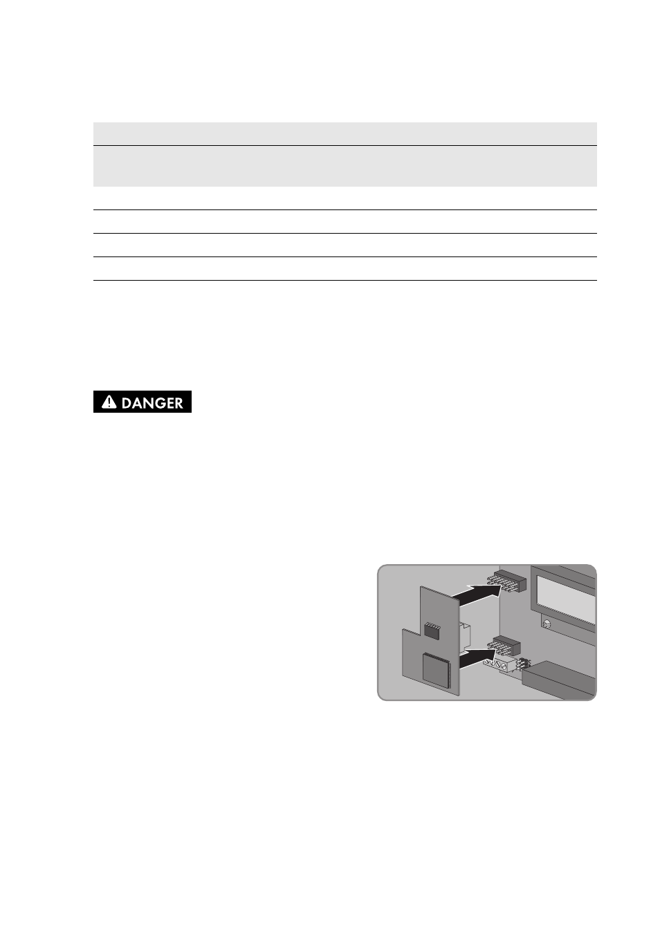
5.4 Installing the Piggy-Back
2. Plug the Piggy-Back into the female connectors at
the slot in the inverter (for position of slot, see
Section 5.1).
3. Stick one of the labels with the data for registration in Sunny Portal (PIC and RID) on the outside
of the inverter in the vicinity of the type label.
4. Close the inverter (see inverter installation manual).
Network cable
Signal
Pin RJ45 plug
EIA/TIA 568A (8-wire)
Wire colour
Profinet (4-wire)
Wire colour
TD+
1
white/green
yellow
TD-
2
green
orange
RD+
3
white/orange
white
RD-
6
orange
blue
1.
Danger to life due to electric shock when opening the inverter
Lethal voltages are present in the conductive parts of the inverter.
• If the inverter is closed, proceed as follows:
• Disconnect the inverter from any voltage sources on the AC and DC sides (see the
inverter installation manual). Observe the waiting time to allow the capacitors to
discharge.
• Open the inverter (see inverter installation manual).