4 specifications – SMA FLX Series Sensor Interface Option User Manual
Page 10
4 Specifications
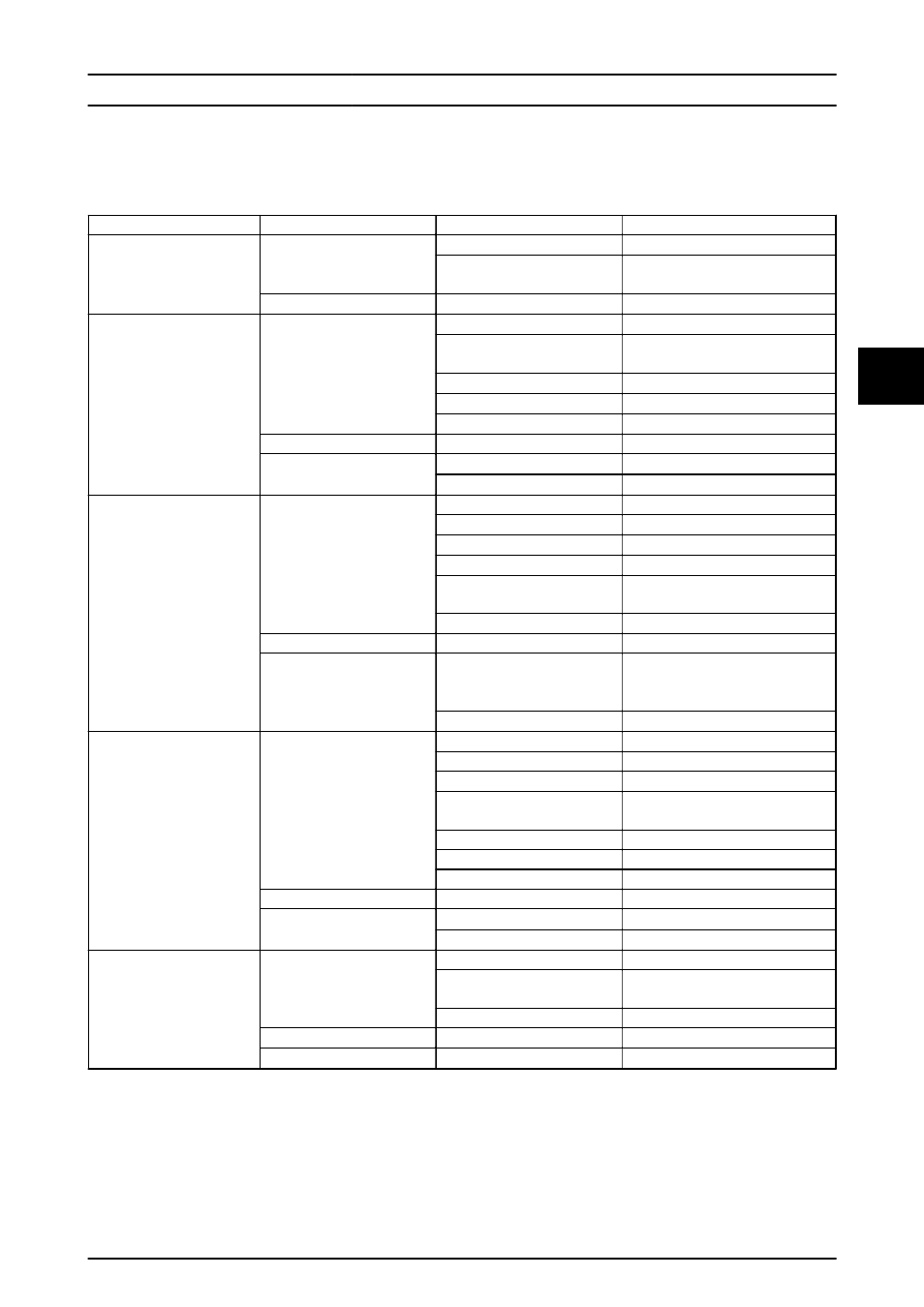
Terminal
Parameter
Parameter Details
Specification
All terminals
Wiring terminal
Maximum wire gauge, solid wire
1.5 mm
2
Maximum wire gauge, stranded
wire
1.0 mm
2
Cabling
Cable jacket diameter (
⌀)
4-8 mm
Temperature sensor input
TEMP MOD
TEMP AMB
TEMP IR.
Sensor input
Sensor type
3 x PT1000
3)
Nominal resistance/temperature
coefficient
3.85
Ω/
o
C
Measurement range
-20
o
C - +100
o
C
Measurement accuracy
±2
o
C
Short-circuit protection
Yes
Electrical safety
Direct contact protection
Double/Reinforced insulation
Cabling
Cable type
Single pair - 2-wire
1)
Maximum resistance per wire
2)
2
Ω
Irradiation sensor input
IR+
IR-
Sensor input
Sensor type
Current shunt (passive)
Measurement range
0 - 150 mV
Max. output impedance (sensor)
500
Ω
Input impedance (electronics)
24 k
Ω
Measurement accuracy
±5 % at 150 mV sensor output
voltage
Short-circuit protection
Yes
Electrical safety
Direct contact protection
Double/Reinforced insulation
Cabling
Cable type
Single pair - 2-wire
1)
Two pairs - 4 wires with temperature
compensation
Maximum resistance per wire
2)
10
Ω
Energy meter input
S0+
S0-
Sensor input
Sensor type
S0 output device
Sensor input class
Class A
Nominal output current
12 mA for an 800
Ω load
Maximum short-circuit output
current
24.5 mA
Open-circuit output voltage
+12 VDC
Maximum pulse frequency
16.7 Hz
Short-circuit protection
Yes
Electrical safety
Direct contact protection
Double/Reinforced insulation
Cabling
Cable type
Single pair - 2-wire
1)
Maximum resistance per wire
2)
10
Ω
Relay output (normally open)
RELAY (NO)
Relay output
Relay type
Potential free contact
Rating AC
250 VAC maximum permitted voltage,
1.0 A, 230 W
Rating DC
24 VDC, 1.0 A, 24 W
Electrical safety
Overvoltage category
Class III
Cabling
Cable type
Single pair - 2-wire
1)
Table 4.1 Sensor Interface Specifications
1)
Shielded or unshielded cables may be used.
2)
Cable resistances will result in a measurement offset.
3)
3
rd
input is used for compensation of the irradiation sensor.
Specifications
L00410607-02_2q / Rev. date: 2014-06-20
9
4
4