ShoreLand'r LUV2314SW V.2 User Manual
Page 8
Midwest Industries, Inc.
Ida Grove, IA 51445
800.859.3028
www.shorelandr.com
0003808
Page 8
06/05/07
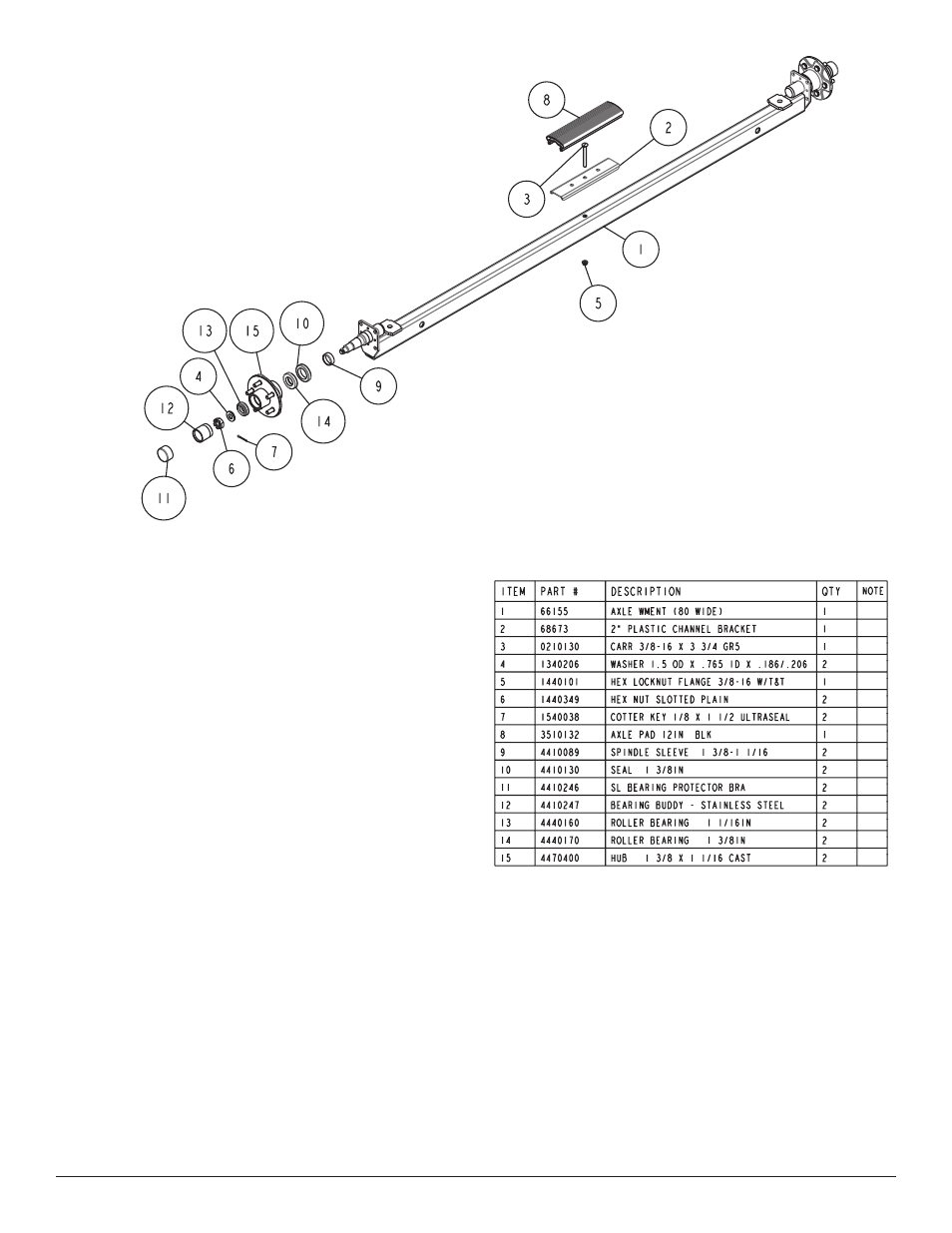
ITEM
PART #
DESCRIPTION
QTY
NOTE
1
66155
AXLE WMENT (80 WIDE)
1
2
68673
2" PLASTIC CHANNEL BRACKET
1
3
0210130
CARR 3/8-16 X 3 3/4 GR5
1
4
1340206
WASHER 1.5 OD X .765 ID X .186/.206
2
5
1440101
HEX LOCKNUT FLANGE 3/8-16 W/T&T
1
6
1440349
HEX NUT SLOTTED PLAIN
2
7
1540038
COTTER KEY 1/8 X 1 1/2 ULTRASEAL
2
8
3510132
AXLE PAD 12IN BLK
1
9
4410089
SPINDLE SLEEVE 1 3/8-1 1/16
2
10
4410130
SEAL 1 3/8IN
2
11
4410246
SL BEARING PROTECTOR BRA
2
12
4410247
BEARING BUDDY - STAINLESS STEEL
2
13
4440160
ROLLER BEARING 1 1/16IN
2
14
4440170
ROLLER BEARING 1 3/8IN
2
15
4470400
HUB 1 3/8 X 1 1/16 CAST
2
1
2
3
4
5
6
7
8
9
10
11
12
13
14
15
SPRINGS
Position the axle so it is properly aligned with the trailer and the
calipers are on the back side of the axle as shown.
Place the springs on the topside of the spring pads welded to the
axle.
(See Diagram D). Note that the hook end of the spring must
be mounted to the rear of the trailer. Place a spring clamp on the
top center of the spring as shown. Next place the 1/2” x 6-1/2”
U-bolts down over the top of the spring clamp, spring and axle as
shown.
Place the spring and axle U-bolt plate onto the ends of the two
U-bolts just placed around the axle. Secure with 1/2” lock nuts.
Thread onto the U-bolts but do not tighten securely until the com-
plete unit is in position on the trailer. Repeat on the other spring.
AXLE
Place one of the spring bracket bushings into the rear of the spring
bracket and secure with a 9/16” x 3-1/4” hex bolt and hex lock nut.
Repeat in other spring bracket.
Position the axle under the frame, then hook the hook loop of the
spring around the bushings just installed. Note that if the axle is
positioned too low when trying to hook, the hooks will not hook
around the bushings.
Raise the front of the springs up so they align with the front hole
of the spring bracket. Secure in place with 9/16” x 3-1/4” hex bolts
and lock nuts.
Tighten all axle U-bolts and spring bolts not tightened at this time.
TIRE & WHEEL ASSEMBLIES
Mount the tire and wheel assemblies using the 1/2” fine threaded
tapered lug nuts provided. Tighten to 85-95 ft/lb. of torque using the
rotation pattern as shown in the ShoreLandr’s Owners Manual.
Re-torque the lug nuts after 50 miles of driving and then periodi-
cally thereafter.