Diagram c – ShoreLand'r LUV2314SW V.2 User Manual
Page 5
Midwest Industries, Inc.
Ida Grove, IA 51445
800.859.3028
www.shorelandr.com
0003808
Page 5
06/05/07
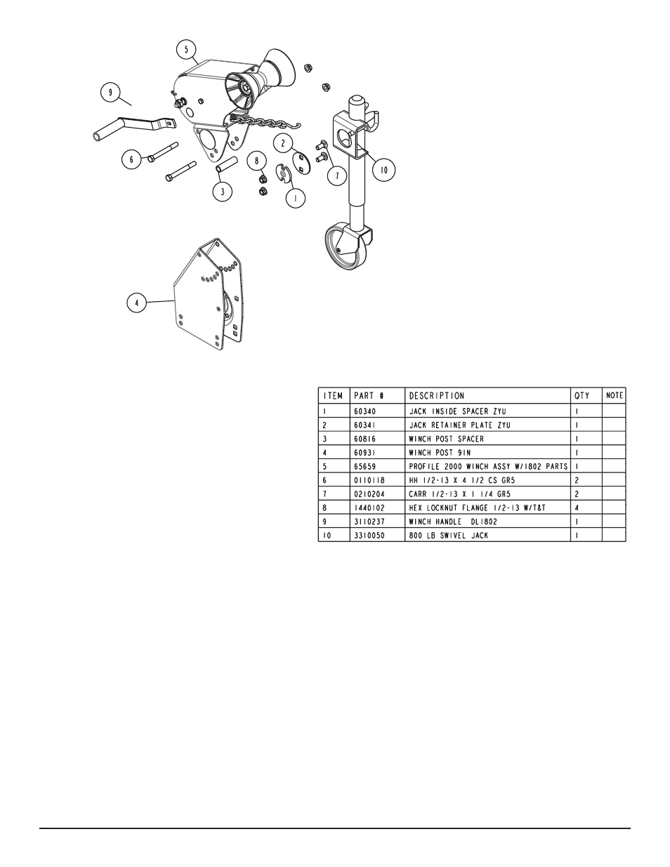
Diagram C
ITEM
PART #
DESCRIPTION
QTY
NOTE
1
60340
JACK INSIDE SPACER ZYU
1
2
60341
JACK RETAINER PLATE ZYU
1
3
60816
WINCH POST SPACER
1
4
60931
WINCH POST 9IN
1
5
65659
PROFILE 2000 WINCH ASSY W/1802 PARTS
1
6
0110118
HH 1/2-13 X 4 1/2 CS GR5
2
7
0210204
CARR 1/2-13 X 1 1/4 GR5
2
8
1440102
HEX LOCKNUT FLANGE 1/2-13 W/T&T
4
9
3110237
WINCH HANDLE DL1802
1
10
3310050
800 LB SWIVEL JACK
1
1
2
3
4
5
6
7
8
9
10
is going to be mounted on is up.
Place the inside jack spacer on the winch base so the center pro-
trusion fits down into the indent in the winch base.
Position the jack mounting plate so it is centered around the inside
jack spacer just positioned.
Lay the jack retainer plate on top of the jack mounting plate aligning
the holes in it with the holes in the winch base.
Insert the two ½” and 1 ¼” carriage bolts into the holes just aligned
in the jack retainer plate and the winch base. Secure in place with
½” lock washers and hex nuts. Tighten.
Once tightened, rotate the jack through its normal pivoting range to
make sure it is free to travel and is not binding up.
If jack pivots, place it on the tongue and secure in place with the
bolts and hardware provided with the trailer. Complete the assem-
bly of the winch head to the winch base. Assembly is complete.
WINCH POST INSTALLATION
The height that the bow eye is placed in your boat will determine
the length winch post required. Once this is determined, attach the
winch base to the tongue with three 1/2” x 4” carriage bolts and
lock nuts.
Align the holes in the Profile 2000 mounting channel with the
holes in the top of the winch base. Attach the front of the winch
head mounting channel to the base by placing a 1/2” x 4” hex bolt
through the hole closest to the front of the winch base. Secure with
a lock nut. Do not tighten.
Note that the winch head can now be rotated either up or down.
Identify the correct hole combination to use to position the bow eye
roller just above the bow eye of your boat. When determined, se-
cure in this position by placing the bushing as shown in
Diagram C
inside the winch base so it aligns with the hole just identified for the
proper adjustment. Insert another 1/2” x 4-1/2” hex bolt through the
determined mounting hole in the mounting channel and winch base
making sure the bolt passes through the bushing as well. Secure
with a 1/2” lock nut. Tighten all bolts.