ShoreLand'r SLB10 V.3 User Manual
Page 6
Midwest Industries, Inc.
Ida Grove, IA 51445
800.859.3028
www.shorelandr.com
M308185
Page 6 of 8
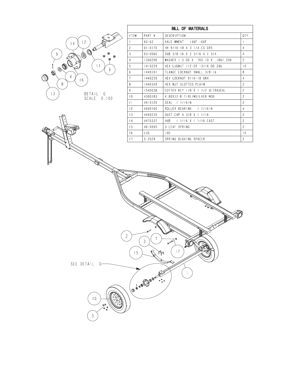
Springs
See Diagram. Place a spring bushing spacer
(Ref. No. 17) up inside the legs of the rear
spring loop of the spring bracket, then
insert a 9/16” x 3-1/4” hex fine threaded
spring bolt through the spring bracket and
the spring bushing spacer just installed.
Secure with a 9/16” hex fine threaded nut.
Locate a spring. Slip the flat end of the spring
inside the rear spring bracket loop above the
spring bushing spacer just installed. Attach
the front of the spring to the front spring loop
using another 9/16” x 3-1/4” hex fine
threaded spring bolt and hex fine threaded
nut. Tighten. Repeat this process on the
other spring.
Axle
Raise the axle up under the springs. Align
the pin on the bottom of the spring with the
hole provided in the spring mounting plate
welded to the top of the axle. Slide two- 3/8”
x 2-3/16” x 1-3/4” square U-bolts down over
the top of the spring. Align with the holes in
the spring mounting plate on the axle.
Secure the axle to the springs with 3/8” flange
lock nuts. Repeat this process on the other
spring. Tighten all nuts holding the axle to
the springs.
Tire And Wheel Assemblies
Mount the tire and wheel assemblies using
the 1/2” fine threaded tapered lug nuts
provided. Tighten to 80-90 ft/lb. of torque
using the rotation pattern as shown in the
ShoreLandr’s Owners Manual. Re-torque
the lug nuts after 50 miles of driving and then
periodically thereafter.