Nd 287 functions, Switching i/o – HEIDENHAIN ND 287 Quick Start User Manual
Page 8
4
Axis Coupling
Input X2 is available for an additional
input assembly (option). Possible options:
Encoder module for connecting a
•
second encoder
Analog module for connecting an
•
analog sensor with ± 10 V
Descriptions are included with the
modules.
X1 and X2 can be displayed separately
or they can be coupled through
mathematical functions. You can switch
the display by soft key or through a
switching input at any time.
The following axis displays are possible:
Input X1
•
Input X2
•
Sum of X1 and X2
•
Difference between X1 and X2
•
Any function for coupling X1 and X2
•
Special features of coupled
positions
If PRESET is used, X1 is set to the
•
value entered, and X2 is set to zero.
If RESET is used, a value other than
•
zero may be displayed depending on
the programmed formula (e.g.: 5 if
"X1 + X2 + 5").
The values of the currently active axis
•
display are used for SPC.
If two axes are coupled, the fi ner of
•
the two display resolutions will be
used.
If axis values are used as divisors,
•
division by zero or display overfl ow
may cause a temporary error
message.
If an analog sensor is connected to
•
input X2 and the ENCODER TYPE
fi eld under Encoder Setup, Input X2 is
set to COMPENSATION, the ND 287
behaves in the same way as a
single-axis display unit.
If COMPENSATION is selected, the
•
formula for axis-error compensation is
determined automatically. You only
enter the coeffi cient of expansion and
the reference temperature.
Pin Layout
PIN
Version 1
Version 2
1
0 V
2 I
Reset, clear error message
3 I
Set the datum
4 I
Ignore reference mark signals (input X1)
5 I
Start measurement series
f(X1,X2) display
6 I
Select display value for meas. series externally
X1 display
7 I
Display the minimum value (MIN) of the meas. series
X2 display
8 I
Display the maximum value (MAX) of the meas. series
X1+X2 display
9 I
Display the difference MAX-MIN of the meas. series
X1-X2 display
10
0 V
11
Free
12
Do not assign
13
Do not assign
14
O
Display value is zero
15
O
Measured value is greater than or equal to trigger limit A1
16
O
Measured value is greater than or equal to trigger limit A2
17
O
Measured value is less than the lower sorting limit
18
O
Measured value is greater than the upper sorting limit
19
O
Error
20
Free
21
Free
22
I
Measured value output (pulse)
23
I
Measured value output (contact)
24
I
Ignore reference mark signals (input X2, optional)
25
I
Activate or deactivate REF mode
I: Switching input; O: Switching output
Version 1 or 2 can be selected in Function External Inputs in the Job Setup menu.
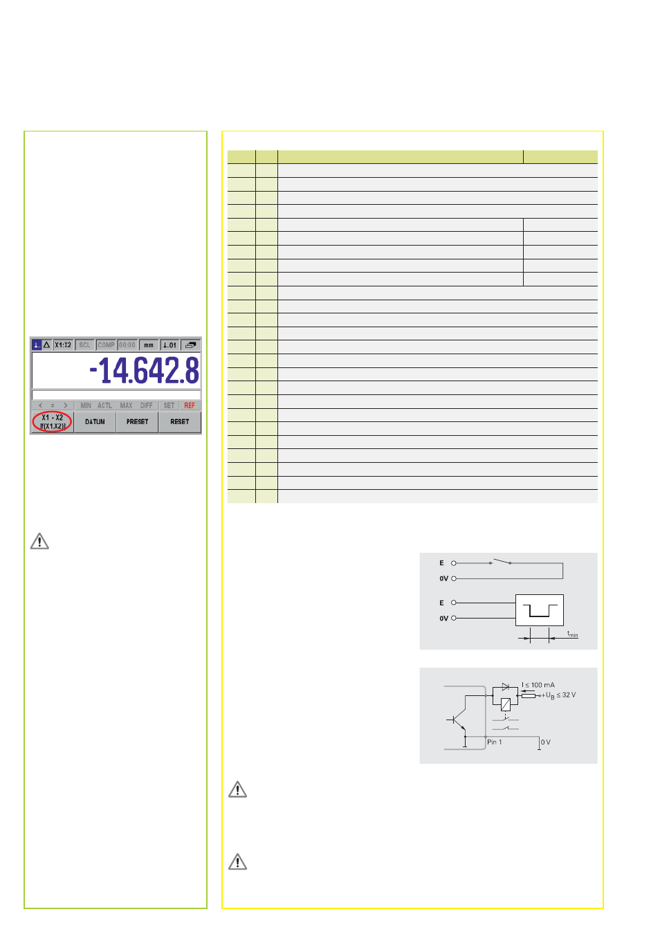
Switching Inputs
The switching input E is active
when a Low signal U
L
is applied
(contact or pulse to 0 V).
Signal level
– 0.5 V † U
L
† 0.9 V at I
L
† 6 mA
3.9
V
† U
H
† 15.0 V
t
min
‡ 30 ms
Switching Outputs
The ND 287 features open-collector
outputs that switch to 0 V (= active Low).
Delay of signal output:
t
D
† 20 ms
Signal level
U
L
† 0.4 V at I
L
† 100 mA
U
H
† 32 V at I
H
† 10 µA
Danger to internal components!
The power supply of external circuits must comply with EN 50
•
178 requirements for
low voltage electrical separation.
Connect inductive loads only with a
•
quenching diode parallel to the inductance.
Use only shielded cables.
•
Connect the shield to the connector housing.
In the Distance-To-Go operating mode, the switching outputs A1 (pin 15) and A2
(pin 16) are based on switching ranges.
ND 287
Functions
For detailed description, see
www.heidenhain.de
Switching I/O
Contact
Pulse