Pdx218 scsi cable connections – Grass Valley PDX 218 User Manual
Page 27
PDX218 SCSI Cable Connections
PDX 218 Instruction Manual
2-9
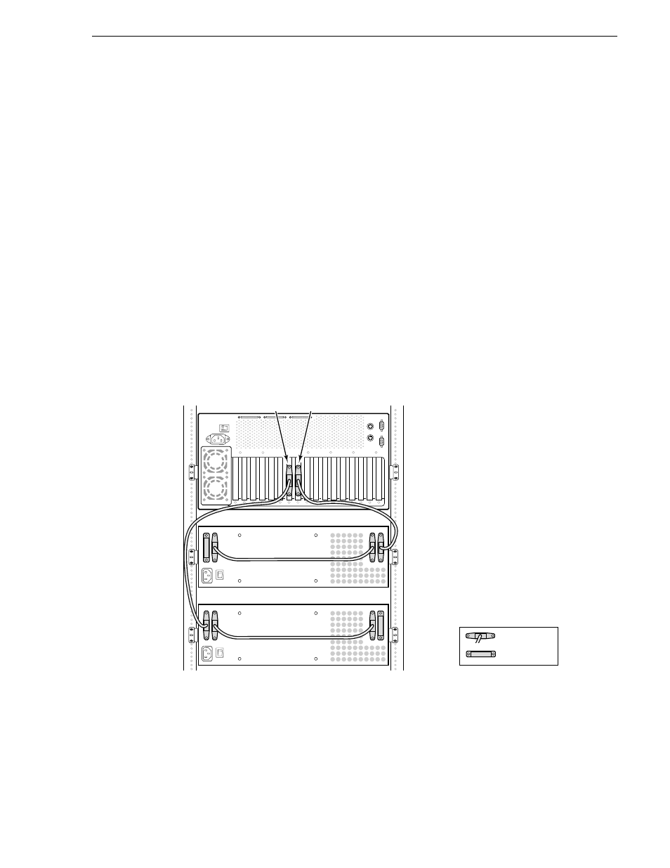
Two PDX218s Connected to a Profile System with Two Disk Recorder Boards
Figure 2-9 shows a PDX 218 connected to a Profile system with Master and Slave
Disk Recorder boards installed. The location of the Disk Recorder boards may be
different than shown in Figure 2-9. To locate the Disk Recorder boards in your
system, see the rear panel board slot labels.
To connect two PDX218s, refer to Figure 2-6 and Figure 2-9 and:
1. Connect a SCSI cable from the first PDX218 SCSI Bus 2 connector to the Profile
system rear panel connector in the slot labeled DISK RECORDER Master.
2. Connect a SCSI cable between the SCSI Bus 1 and SCSI Bus 2 connectors on the
first PDX 218.
3. Connect a Terminator to the unused SCSI Bus 1 connector on the first PDX 218.
4. Connect a SCSI cable from the second PDX218 SCSI Bus 1 connector to the
Profile system rear panel connector in the slot labeled DISK RECORDER Slave.
5. Connect a SCSI cable between the SCSI Bus 1 and SCSI Bus 2 connectors on the
second PDX 218.
6. Connect a Terminator to the unused SCSI Bus 2 connector on the second PDX 218.
Figure 2-9. Connecting Two PDX218s to a Profile System with Master and Slave Disk Recorder Boards
The connection shown in Figure 2-9 provides eight 18GB disk drives to the SCSI A
bus and eight 18GB disk drives to the SCSI C bus on the Profile system (or SCSI A
and SCSI B bus on the PDR100).
9687-24
Terminator
SCSI Cable
First PDX218
Second PDX218
Profile Video
File Server
Disk
Recorder
Master
Disk
Recorder
Slave
Note:
Disk recorder board locations may be
different than shown. See rear panel
labels for actual locations.