Detail – Grass Valley NV5256 v.1.8 User Manual
Page 25
NV5256 Machine Control Router • User’s Guide
17
3. Detail
Alarms
S
Pins 2 through 8 signal alarm conditions that are signalled on either the primary or secondary
control cards. The connector offers no way to distinguish which control card has an alarm.
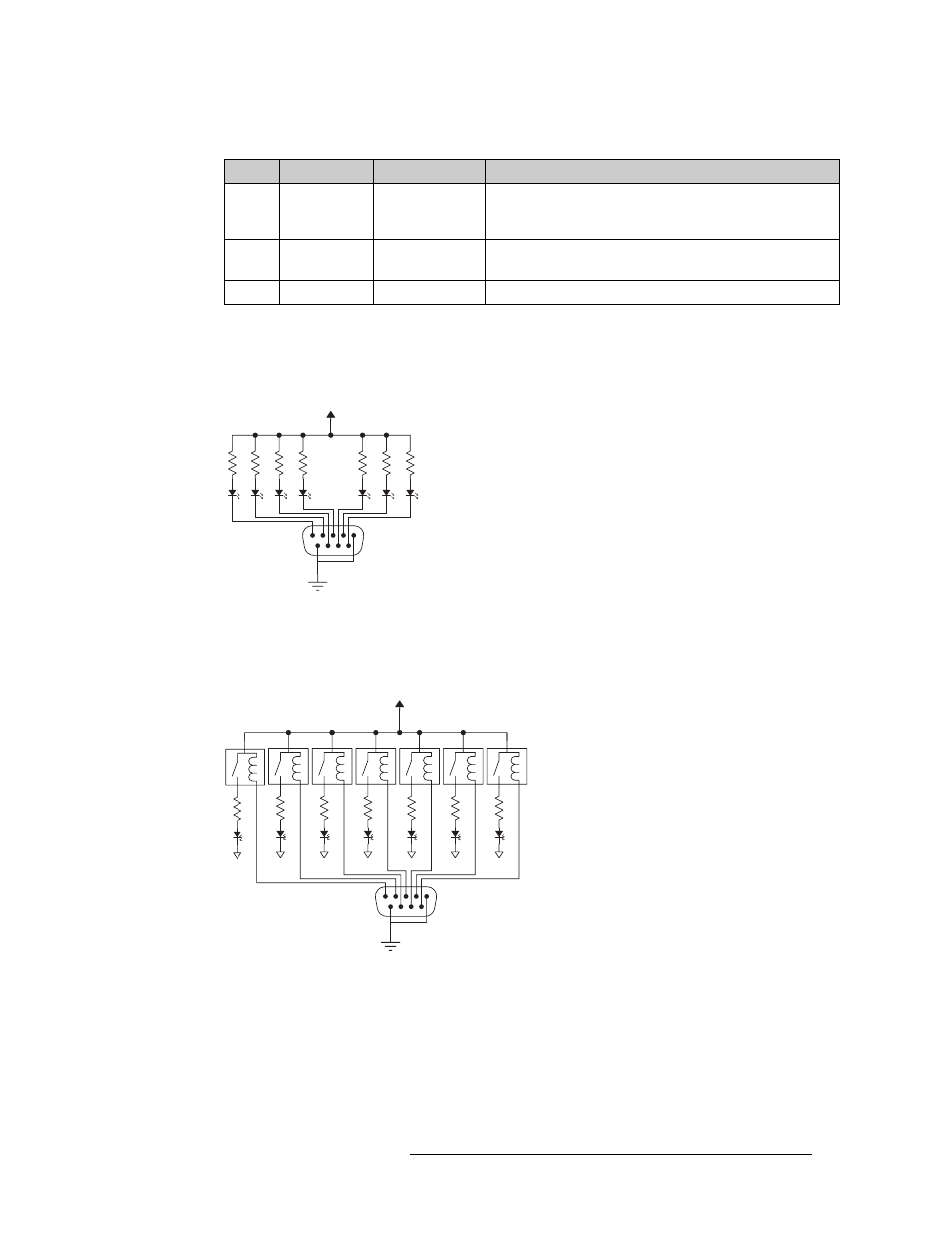
Figures 3-1 and 3-2 show sample system-level alarm circuits. (You can use alarm signalling
devices other than LEDs, or in addition to LEDs.)
Figure 3-1. Simple Alarm Circuit
Here, LEDs are all off unless a failure occurs. The LED for the failed circuit turns on.
This is an alarm circuit that can drive heavier loads, not just LEDs.
Figure 3-2. Alarm Circuit to Drive Loads
In this case, the LEDs are normally on and turn off when a failure occurs.
CAUTION: If the alarm load is inductive, protect the internal alarm relay contacts with a reversed-
biased diode. The external supply voltage should not exceed ±30VDC and the load resistors should
be sized to limit contact current to less than 150mA.
6
Alarm 5
AES or time code
reference
Missing AES reference signals or loss of system clock. (AES
is optional. Note: AES does not generate alarm in standalone
case.)
7
Alarm 6
Fans or internal
Temperature
Failure of any one of three fans. Over-temperature conditions
on one or more modules.
8
Alarm 7
Controller health
Control card(s) are not “healthy.”
Table 3-1. Alarm Signals
Pin
Signal
Description
Possible Alarm Condition(s)
1
COM
Internal alarm signals normally
clear, controlled by software
Normally off, the LEDs
turn on to indicate failure
30VDC max, 150mA max
External Power
Customer-supplied relay
contacts NC, (but open during
alarm condition)
Internal alarm signals normally
clear, controlled by software
External Power,
30VDC max, 150mA max
Normally on, the LEDs turn
off to indicate failure
1
COM