K-frame cabling, Overview, Section 3 — k-frame cabling – Grass Valley K-Frame Installation Planning Guide User Manual
Page 41
K-FRAME — Installation Planning Guide
41
Section
3
K-Frame Cabling
Overview
A K-Frame Video Processor uses Ethernet for basic system communica-
tions, can operate with Kayenne or Karrera control surfaces, supports
several video inputs and output standards, and has other available inter-
faces (RS-232, Tally, GPI).
Note
Specific Kayenne and Karrera control surface cabling information is provided
in each product’s separate documentation sets. One important difference is
Kayenne systems incorporate the Menu PC and Control Panel electronics into
a Panel Control Unit (PCU) chassis,
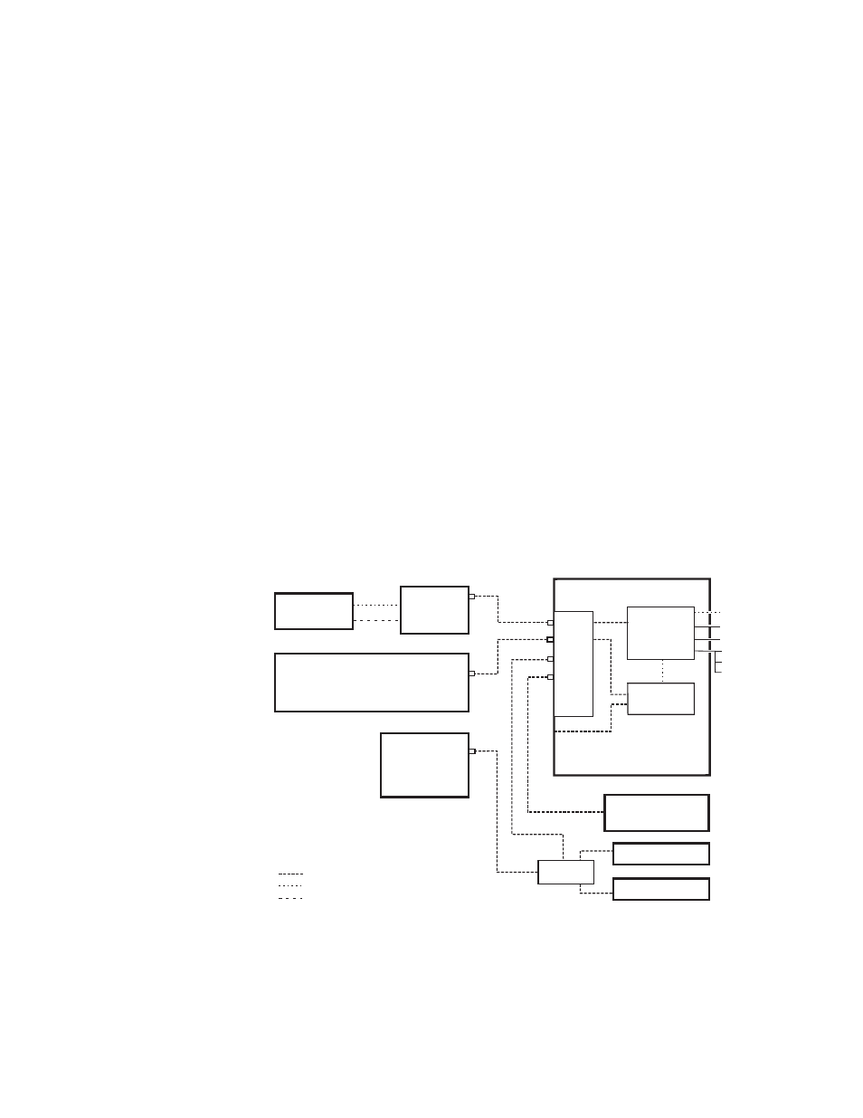
Figure 1. K-Frame System Communications Overview
CAUTION The facility network used for your K-Frame system (and other video produc-
tion equipment) should be kept separate from any external network, to
prevent network traffic from adversely affecting K-Frame system operation.
8875_16
Operator’s
Laptop
Disable Internet or
Wireless Connections
Isolate Switcher System from External Network
Internal Control
K-Frame Video Processor
Video
Processor
CPU
Image Store
Eh
te
rne
t Swi
tch
1
2
3
4
5
6
7
8
Menu
PC
Menu Panel
Remote Aux Panel
Remote Aux Panel
Clip Store
Facility LAN
Switch
Switcher Control Panel
USB (4)*
Keyboard, VGA*
RS-232*
RS-422/485 (8)
GPI In/Out
Tally
USB
DVI-D
Ethernet
Serial Control
VGA
Ethernet
(100m / 300ft max single hop length,
unlimited distance using switches)