6ru rear view, K-frame controller connections – Grass Valley K-Frame Installation Planning Guide User Manual
Page 30
30
K-FRAME — Installation Planning Guide
Section 2 — K-Frame Installation
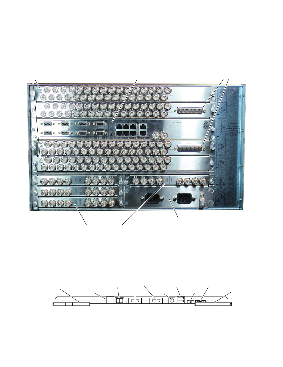
6RU Rear View
Figure 11. K-Frame 6-RU, Rear View
K-Frame Controller Connections
Figure 12. K-Frame Controller Board, Inside Chassis
8875_08r1
Output Video
(16 outputs)
Up to 2 modules
Module 4 Module 1
Modular I/O
Up to 4 modules
Control I/O
(Reference,Ethernet
and Serial ports)
Input Video
(32 inputs,
8 GPI in/out, and 24 Tally)
Up to 2 modules
Power Supply
AC
ON
OFF
Boot Mode
DIP Switch
Power
Switch
8875_10
LEDs (15)
Test Points
with LEDs (9)
and Text Display
Reset
Button
RS-232
PS2
Keyboard
VGA
USB
(two ports, usable
with door closed)
USB
(two ports)
NOTE: Ports and indicators here are intended only for diagnostic and service procedures.
This manual is related to the following products: