K-frame standard power supply frame installation – Grass Valley K-Frame Installation Planning Guide User Manual
Page 31
K-FRAME — Installation Planning Guide
31
K-Frame Standard Power Supply Frame Installation
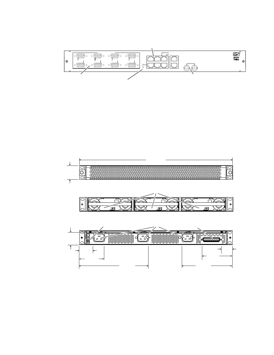
Figure 13. Controller I/O Connections, Rear of Chassis
K-Frame Standard Power Supply Frame Installation
A 1-RU Power Supply Frame provides DC power for the Standard, 13RU
K-Frame Video Processor.
Figure 14. K-Frame 13RU Power Supply Frame Dimensions (Front and Rear Views)
LINK/ACTIVITY
OFF-10/AMBER-100/GREEN-1000
LAN
ANALOG
REFERENCE
DIAGNOSTIC
MODE
8
7
6
5
4
3
2
2
4
6
1
3
5
1
SERIAL PORTS RS422/485
8875_18r1
Illuminated LED indicates
Port 1 is in diagnostic mode
Reference
Serial Ports (8)
RS422/486
Ethernet (6)
(communications)
482 mm
19.0 in.
Front View Cover Removed
Front View with Cover
Rear View
8875_11
44 mm
1.72 in.
45 mm
1.8 in.
79 mm
3.1 in.
217 mm
8.5 in.
38 mm
1.5 in.
159 mm
6.3 in.
36 mm
1.4 in.
97 mm
3.8 in.
Grounding Lug
AC Input IEC C19 (3)
Power Modules (up to 3)
DC Power Out
(to K-Frame)