Grass Valley AAP-1741 User Manual
Page 16
GUIDE TO INSTALLATION AND OPERATION
12
| AAP-1741
3.3.1 Audio
Processing
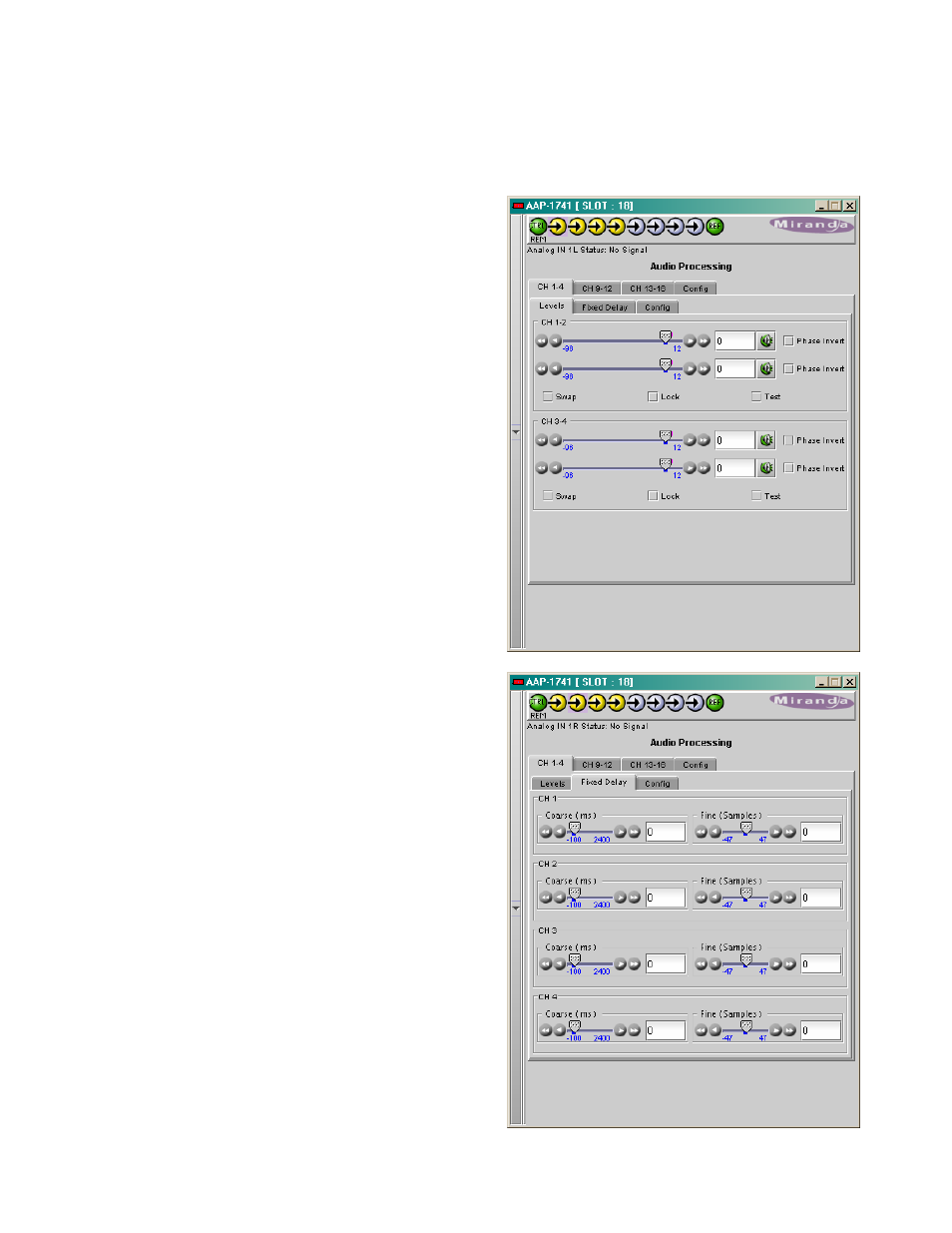
3.3.1.1 Audio Processing - CH 1-4 to CH 13-16 tabs
The channels 1 to 4 are the analog inputs. When a
video card is present, eight extracted audio
channels are available as Channel 9 to Channel
16,
see ABUS Input Section (page 23).
Each of these tabs controls the input processing:
Levels, Fixed Delays and configuration for the
absence signal detection for two pairs of channels;
each channel is provided with a set of controls.
Levels
sub-tab: grouped by pair of channels, each
channel has the following controls: a Level slider
(from -96 to 12 dB), an input box where the desired
level may be input directly, a Mute icon button and a
Phase Invert checkbox.
At the bottom are three checkboxes:
• Swap – allows channel swapping inside a
pair.
• Lock – locks both channel sliders together for
levels and delay, so that moving one slider
moves the other one as well.
• Test – replaces the input signal with a stereo
test tone.
Fixed Delay
sub-tab: adds an audio delay to the
signal. For each channel, two sliders allow delay to
be adjusted.
• Coarse – adjusts the delay in ms, from -100
ms to 2400 ms
• Fine – adjusts the delay in sample
increments, from -47 to 47.
Input data boxes are available to enter numerical
values directly.
The negative values will be applied only when the
AAP-1741 is slave of a video card via ABUS. The
positive small values desired have to be larger than
the minimum processing delay to be effective.