Figure 9 – Grass Valley 8920ADT User Manual
Page 24
18
8920ADT Instruction Manual
8920ADT Analog Audio to AES/EBU Converter with Delay Tracking
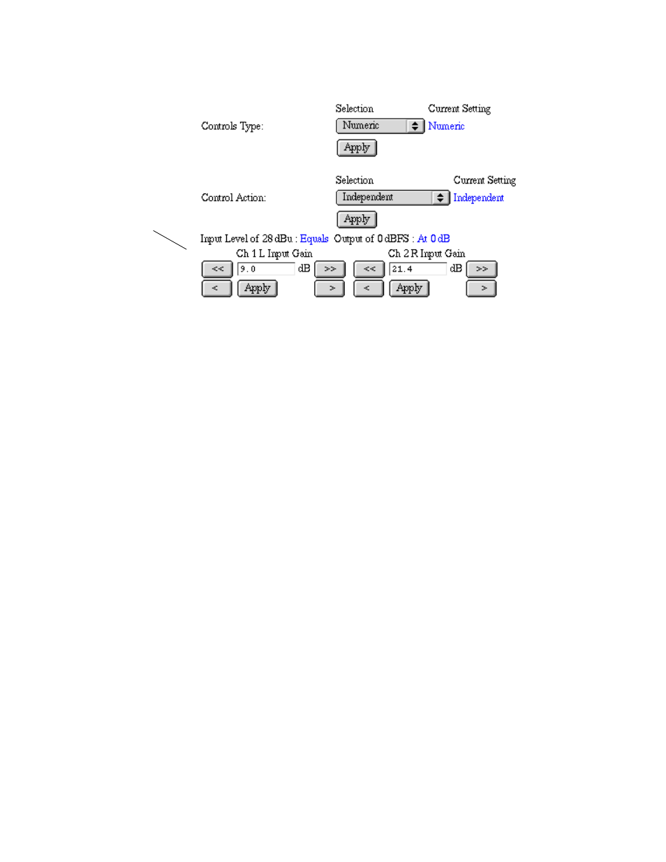
Figure 9. Numeric Control Mode for Level Adjustment
The following status items will be reported in this display (see
■
Model name — as defined on the main Status page.
■
Frame location — indicates the frame name and slot number.
■
Left and Right Ch > -20 dBFS — indicates whether the left and right
channel digital output levels are greater than -20 dBFS (True) or less
than -20 dBFS (False).
■
Left and Right Ch > -0.5 dBFS Clip — indicates whether the digital
output clipping levels are greater than -0.5 dBFS (True) or less than -0.5
dBFS (False).
■
Reference Signal — indicates one of these reference signal input condi-
tions:
■
No reference signal present,
■
AES signal present,
■
525 video signal present,
■
625 video signal present, or
■
48 kHz Word Clock signal present.
■
Output Audio Bit Res. — 20-bit or 24-bit digital output (Jumper selec-
tion, see
).
Numeric Entry Mode