Switches and the paddle switch shown in, Switch sw 3. refer to, Table 6 – Grass Valley 8920ADT User Manual
Page 16: For details
10
8920ADT Instruction Manual
8920ADT Analog Audio to AES/EBU Converter with Delay Tracking
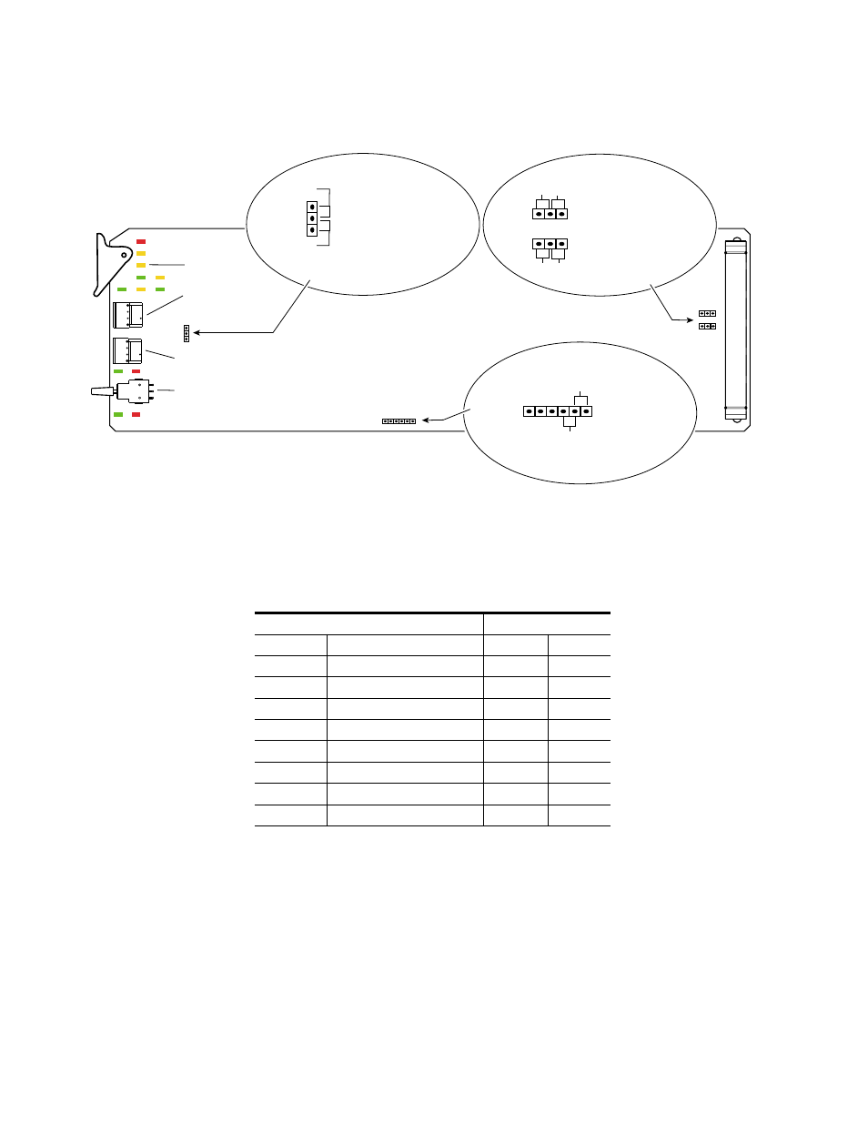
Figure 5. Module Configuration Switches and LEDs
gives the functions of each selection on the Control rotary switch
(SW 1) and the action of the paddle switch (SW 3) in each function.
Table 6. Control Rotary Switch Function Selections
Control Switch
Paddle Switch
Position
Function
Up
Down
0
Disable paddle control
–
–
1
Level adjust for both channels
†
†
Any offset between the channels will be maintained in this adjustment.
Increase
Decrease
2
Level adjust for left channel
Increase
Decrease
3
Level adjust for right channel
Increase
Decrease
4
Delay
Increase
Decrease
5 – D
Disable paddle control
–
–
E
User settings
Recall
Save
F
Factory settings
Recall
–
8067_05
Jumpers across pins
5 – 6 for 20-bit output
SW 3 – Paddle Switch
CONF (yellow)
Remote Control Lockout
JP4
JP7
JP8
JP6
SW 2 – MODE
Rotary Switch
SW 1 – CONTROL Rotary Switch
Balanced/Unbalanced Outputs
JP4
L & REM
Jumper across
pins 1 – 2
locks out remote control
Jumper across pins 2 – 3
enables remote
and local control
1
LOCAL
Jumpers across
pins 1 – 2
for unbalanced outputs
Jumpers across
pins 2 – 3 for
balanced output
JP7
JP8
1
3
1
3
Unbal
Unbal
Bal
Output Audio Bit Resolution
Jumpers across pins
4 – 5 for 24-bit output
JP6
1
6
Bal