Frame capacity – Grass Valley 8920DAC User Manual
Page 9
8920DAC Instruction Manual
3
Installation
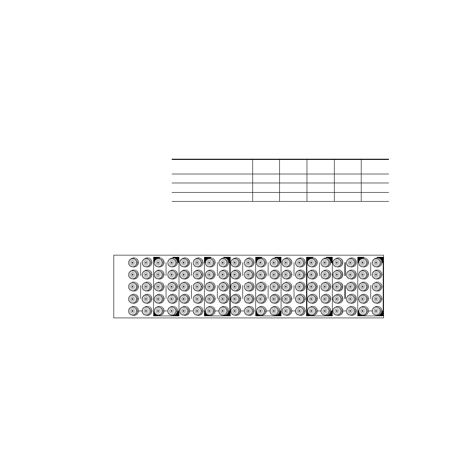
8900 modules are interchangeable within the module cells. There are 10
BNC connectors in each cell’s I/O group. The functional assignment of
each connector in a group is determined by the module that is placed in
that cell. The maximum number of modules an 8900 frame can accept is ten.
illustrates the rear connector plate for an 8900 Series frame.
Frame Capacity
The maximum number of 8900 modules allowed in a frame is determined
by frame cooling capacity.
provides the power capacity, cooling
capacity, and maximum module count for the 8920DAC in each frame type.
Note
Module capacity figures assume no other modules are in the frame. If the
maximum number of modules a frame can handle is less than ten, provide as
much space between the modules as possible.
Figure 2. 8900 Series Frame Rear Connectors
8900 modules can be inserted and removed while the frame is powered. To
install a module in the frame:
1.
Insert the module, connector end first, with the component side of the
module facing to the right and the ejector tab to the top.
2.
Verify that the module connector seats properly against the backplane.
3.
Press the ejector tab in to seat the module in place.
Table 1. Power, Cooling, and Module Capacity of 8900 Frames
Capacity Calculated
8900T2
Frame
8900T2-F
Frame
8900TX
Frame
8900TF
Frame
8900TFN
Frame
Power (W)
60
60
100
100
100
Recommended Module Cooling (W)
30
60
30
90
90
8920DAC Modules
10
10
10
10
10
J1
J2
J3
J4
J5
J6
J7
J8
J9 J10
IN
DA1
J2
J4
J6
J8
J1
J2
J3
J4
J5
J6
J7
J8
J9 J10
IN
DA3
J1
J2
J3
J4
J5
J6
J7
J8
J9 J10
IN
DA5
J1
J2
J3
J4
J5
J6
J7
J8
J9 J10
IN
DA2
J1
J2
J3
J4
J5
J6
J7
J8
J9 J10
IN
DA7
J1
J2
J3
J4
J5
J6
J7
J8
J9 J10
IN
DA9
J1
J2
J3
J4
J5
J6
J7
J8
J9 J10
IN
DA4
J2
J4
J6
J8
J1
J2
J3
J4
J5
J6
J7
J8
J9 J10
IN
DA6
J2
J4
J6
J8
J1
J2
J3
J4
J5
J6
J7
J8
J9 J10
IN
DA8
J2
J4
J6
J8
J1
J2
J3
J4
J5
J6
J7
J8
J9 J10
IN
DA10
O
U
T
O
U
T
O
U
T
O
U
T
O
U
T
O
U
T
O
U
T
O
U
T
O
U
T
O
U
T
0614-03