Level adjustment, 20/24-bit dac operation, Remote control lockout – Grass Valley 8920DAC User Manual
Page 16
10
8920DAC Instruction Manual
8920DAC AES/EBU to Analog Audio Converter
Level Adjustment
The gain stage of each output channel (right and left) has two means of
adjustment—fine and coarse (refer to
The Coarse jumpers (JP6 and JP7) select the range of adjustment either:
■
High range—19 to 24 dBu, or
■
Low range—14 to 20 dBu.
Fine control within those ranges is set using the multi-turn potentiometers
(Left and Right Fine Adj.) providing ±3 dBu gain adjustment (do not exceed
24 dBu). This combination gives a maximum range of full-signal settings
from +14 dBu to +24 dBu.
20/24-bit DAC Operation
Jumper block JP5, pins 1 to 3, determine whether the DAC is in 24-bit or
20-bit mode (see
). With the jumper across pins 1 and 2,
the DAC is in 20-bit mode and will mask the lower four bits of information.
With the jumper across pins 2 and 3, the DAC is in full 24-bit mode.
Remote Control Lockout
When a jumper is placed across pins 5 and 6 of jumper block JP1, module
output mode settings are adjustable from the on-board switches only. To
have both Local and Remote access, set the jumper across pins 4 and 5 (see
).
7
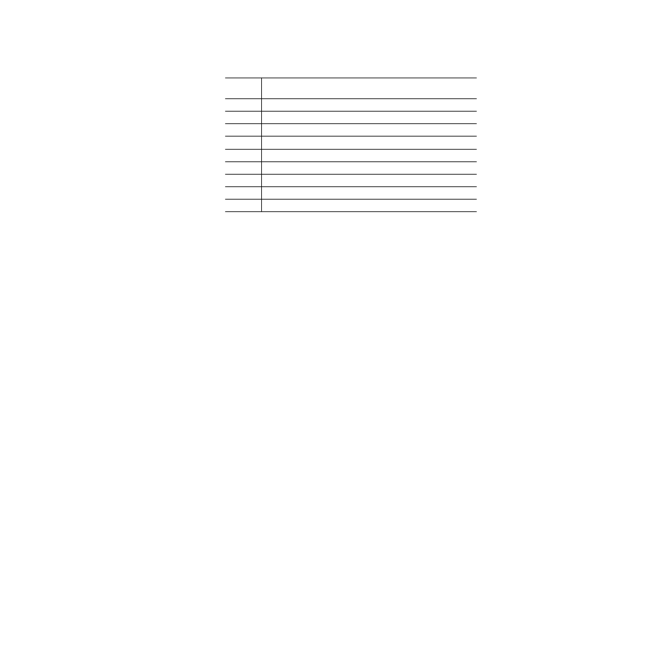
Left + Right to both channel outputs (-6dB mono sum)
8
Left - Right to both channel outputs
9
Left + Right to Left channel output and Left- Right to Right channel output
A
Left + Right to both channel outputs and both channels phase inverted
B
Not Used (Digital Silence)
C
Not Used (Digital Silence)
D
Tone 1 to all channels (Digital Silence)
E
Tone 2 to all channels (1 kHz, -20 dBFS)
F
Factory default – No phase inversion, channel swapping or summing
Table 4. 8920DAC Output Mode Configuration
Switch
Position
Mode Description