2 installation – Grass Valley 3DX-3901 User Manual
Page 7
GUIDE TO INSTALLATION AND OPERATION
3DX-3901 | 3
2 Installation
2.1 Installation in the Densité frame
The 3DX-3901 and its associated rear connector rear panel must be mounted in a Densité-3 frame. It is not
necessary to switch off the frame’s power when installing or removing the card. See the Densité-3 Frame manual
for detailed instructions for installing cards and their associated rear panels.
2.2 Rear
Panels
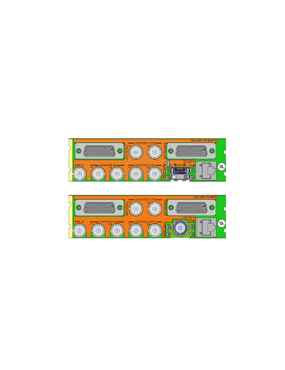
The 3DX-3901 has multiple inputs and outputs, and making space for all the necessary connectors at the rear of
the frame requires a double-width rear panel.
With the double-width rear panel installed, the 3DX-3901 must be installed in the right-most of the two slots
covered by the panel in order to mate with the panel’s connectors.
NOTE: attempting to install the card in the wrong slot could result in damage to the edge connector of the
rear panel. BE CAREFUL
Figure 2.1 Rear Panels for the 3DX-3901
2.3 Connections
For external synchronization, connect a black studio reference signal to the BNC labeled REF IN.
• The reference input is terminated on the rear module.
The reference input must conform to SMPTE 170M/SMPTE 318M/ITU 624-4/BUT 470-6 for standard definition
signals and SMPTE 274M / SMPTE 296M for high definition signals and is used to phase the HD/SD SDI outputs to
the studio. A reference mismatch may occur if there is a difference between the input video format’s frame rate and
the reference format’s frame rate. When a mismatch occurs, the output will freeze to the reference frame rate and
produce an input error and the card-edge Status LED will turn red to indicate the mismatch.
3DX-3901-75-3DRP-F
3DX-3901-75-3DRP