Front panel controls and indicators – Ensemble Designs 5360 Four Channel Analog to Digital Video Converters and Embedders User Manual
Page 11
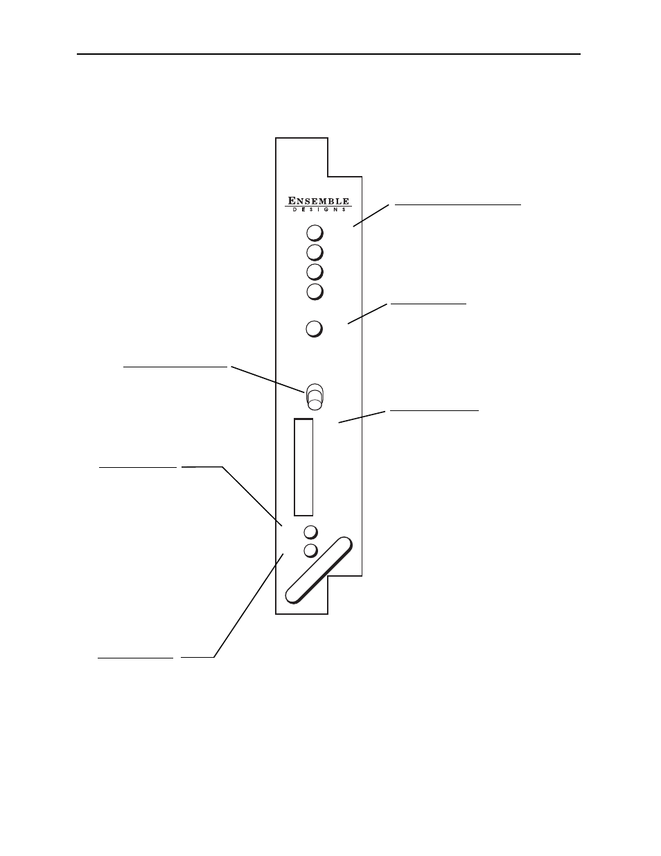
Front Panel Controls and Indicators
Each front edge indicators and switch settings are shown in the diagrams below:
4
Channel
ADC / TBC
Input 1
Input 2
Input 3
Input 4
Ref Pres
Remote
Local
TBC 1
TBC 2
TBC 3
TBC 4
Run
Pwr
5360
on
Remote/Local switch:
Set to the mode you
will be using.
Pwr green LED:
Indicates the presence (ON) or
absence (OFF) of power (+5V).
Run green LED:
OFF:
A power fault or halted CPU
ON:
A halted CPU
FAST BLINK:
CPU Run error
SLOW BLINK:
System OK. (If SPI control
is active from the main
frame System Control
Module, all Run indicators
will be synchronized.)
Ch 1-4 Input green LEDs:
On indicates input video signal
is present and detected on each
individual channel.
OFF no input video signal detected
on the input of each channel.
Ref green LED:
On when the external reference
source is detected.
OFF when no reference signal is
detected.
TBC 1-4 switches:
Turn Time Base Correction On (left)
or Off (right) for each individual
channel with the corresponding
TBC 1-4 switches.
Models 5360 and 5365 Four Channel Analog to Digital Video Converters and Embedders
5360-11