ARAG BRAVO DSB User Manual
Page 8
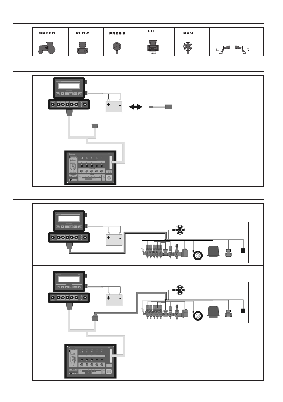
5.2
Correspondence between symbols on DSB and letters on cabling
=
s
=
f
=
M
=
t
=
X
=
r
Tab. 4
5.3
BRAVO DSB connection for simulation/demonstration
Fig. 3
B
c
A
e
d
A • Bravo DSB
B • 5 section “T” cabling
c • Power supply unit
d • Battery
e • Bravo
5.4
BRAVO DSB connection for diagnostics
originAL sYsteM
Fig. 4
c
d
e
insertion of BrAVo dsB
Fig. 5
B
c
A
e
d
A • Bravo DSB
B • 5 section “T” cabling
c • Power supply unit
d • Battery
e • Bravo
8
This manual is related to the following products: