Installation, Assembling & positioning, Hole drilling – Airmar P23 User Manual
Page 2: Plastic shims
Installation
Assembling & Positioning
1. Insert the top of the sensor’s pivot posts into the slots on the top
back of the bracket. Rotate the bracket down until the bottom
snaps onto the sensor.
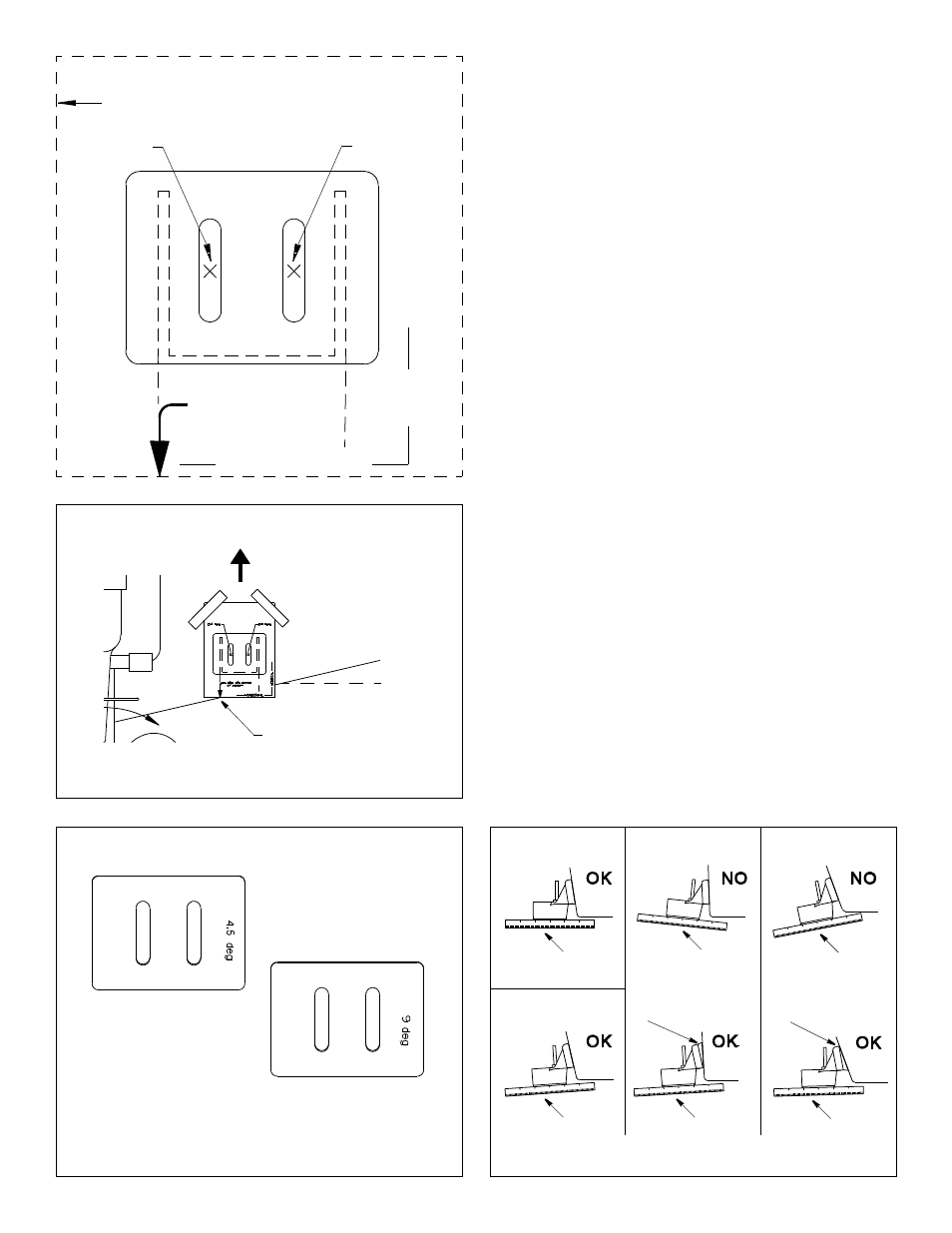
2. Cut out the template (see Figure 2).
3. At the selected location on the starboard side of the hull,
position the template so the arrow at the bottom is aligned with
the bottom edge of the transom (see Figure 3). Being sure the
template is parallel to the waterline, tape it in place.
Hole Drilling
Using a 4mm, #23, or 9/64" bit, drill two holes 22mm (7/8") deep
at the locations indicated. To prevent drilling too deeply, wrap
masking tape around the bit 22mm (7/8") from the point.
Fiberglass hull—Minimize surface cracking by running the drill in
reverse until the gelcoat is penetrated.
Plastic Shims
• Standard transom (13° transom angle)—The bracket is
designed for a standard 13° transom angle. The 9 degree shim
is not needed for this installation. If your boat is capable of
speeds above 35kn (40MPH), install the bracket with the 4.5
degree shim, taper down (see Figures 4 and 5). This ensures
that the paddlewheel will be in contact with the water at high
speeds.
• Stepped transom and jet boats (3° transom angle) —Use the
9 degree shim with the taper down (see Figures 4 and 5).
• Small aluminum and fiberglass boats (20° transom angle)—
Use the 9 degree shim with the taper up (see Figures 4 and 5).
• If you are unsure about using the shims—To determine if the
9 degree shim is needed, position the sensor at the selected
location. Using a straight edge, sight the underside of the
sensor relative to the underside of the hull (see Figures 4 and
5). The trailing edge of the sensor should be 1–3mm (1/16–1/
8") below the leading edge of the sensor or parallel to the
bottom of the hull.
2
Figure 2. Template for starboard side of boat
centerline (keel)
parallel to waterline
vertical
Align this point with
bottom of transom
drill here
drill here
Figure 3. Template position
Align template arrow with
bottom edge of transom
Align template vertically
parallel to
waterline
Figure 4. Plastic shims
thin shim
thick shim
13
° transom angle
14
°
–
17
° angle
Figure 5. Sensor angle adjustment
20
° transom angle
3
° transom angle
parallel
slight angle
angle
reversed
angle
too steep
slight angle
slight angle
shim with taper down
shim with taper up
AIRMAR
®
AIRMAR
®
AIRMAR
®