Airmar P52 with Plastic Release Bracket 20-039 User Manual
Installation instructions owner’s guide, Transom mount, Transducer or triducer
17
-0
03
r
ev.
06
04
/12
/11
Transom Mount
with Release Bracket 20-039
Transducer or TRIDUCER
®
Multisensor
Model: P52
Tools & Materials
Safety goggles
Dust mask
Screwdrivers
Wrenches
Scissors
Masking tape
Electric drill
Drill bits and hole saw or spade bit:
Bracket holes
4mm, #23, or 9/64"
Fiberglass hull
chamfer (preferred), 6mm, or 1/4"
Transom hole (optional)
19mm or 3/4"
20mm or 13/16" (Furuno)
Cable clamp holes
3mm or 1/8"
Marine sealant (suitable for below waterline)
Straight edge
Pencil
Zip-ties
Water-based antifouling paint (mandatory in salt water)
Identifying Your Model
The model name is printed on the cable tag.
Applications
• Not recommended for boat with large inboard engine(s).
• Good operation up to 40kn (46MPH).
• Vertically orients the sound beam on hull with deadrise angle up to 22
°
• Adjusts to transom angles of up to 20
°
Assembly
1. Attach the left release arm to the bracket back by first inserting a hex nut
into the recess in the back of the bracket. Place the arm firmly against
the bracket back and insert a #10-32x5/8" screw with a flat washer
through the holes. Tighten it in place (see Figure 1). Repeat this
procedure with the right release arm.
2. Slide the flat washer and spring onto the #10-32x2" screw and insert it
into the hole in the left release arm. Insert a nylon-insert lock nut in the
right release arm hole with the nylon side facing outward. Tighten the
screw until the spring is flush with the surface of the release arm. Do
not over-tighten.
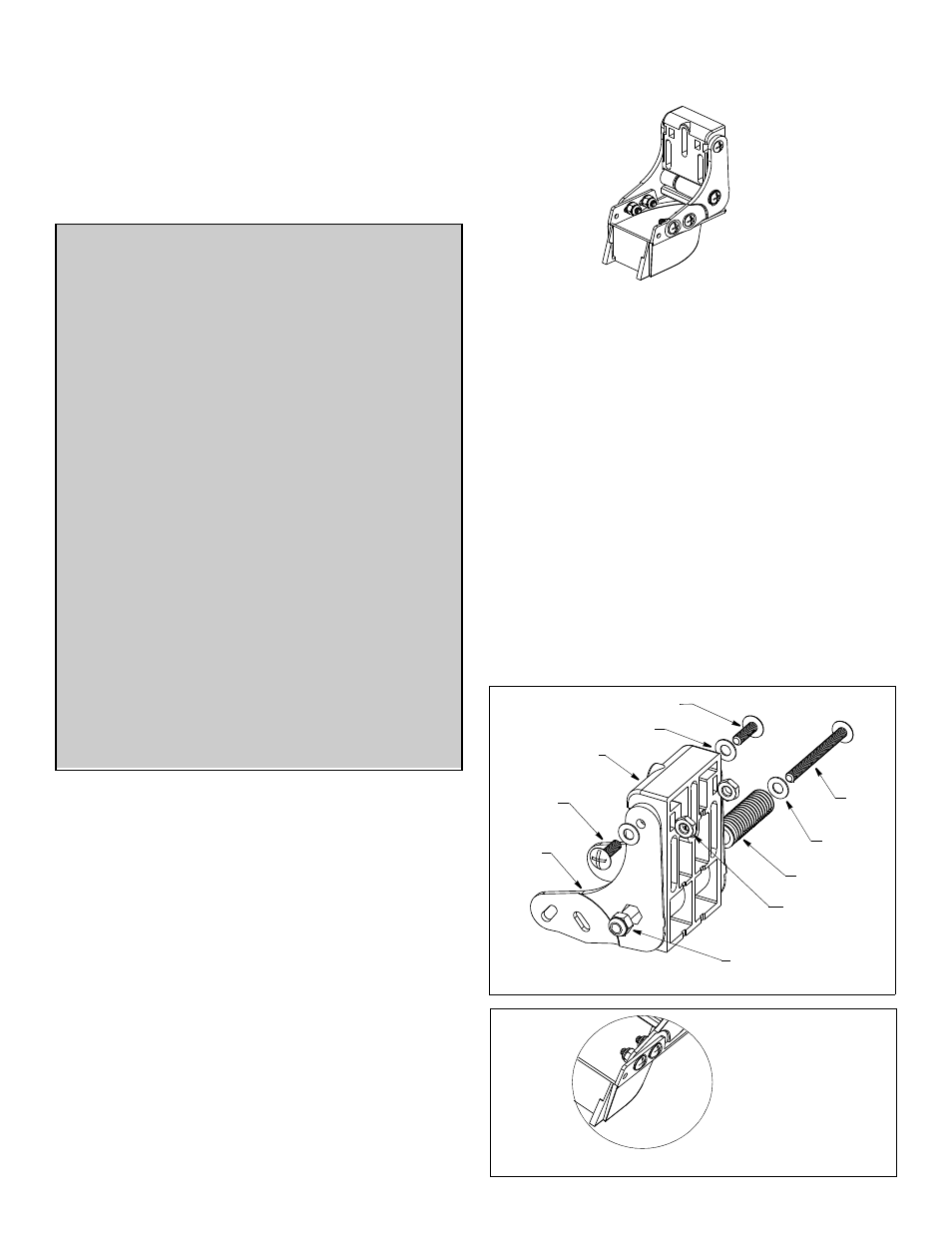
3. P52—Attach the sensor to the bracket by placing the bracket inside
(see Figure 2). Use four #10-32x5/8" screws and flat washers. Fasten
them in place with nylon-insert lock nuts, nylon side facing outward.
Tighten the screws, so the sensor remains in place but can be adjusted.
P37
Figure 1. Bracket assembly
#10-32x2"
#10-32x5/8"
flat washer (3)
nylon insert lock nut
hex nut (2)
spring
right
left
bracket back
screw
screw (2)
release
release
arm
arm
Figure 2. Attaching sensor to bracket
inside
bracket
flat washer
INSTALLATION INSTRUCTIONS
OWNER’S GUIDE &
Follow the precautions below for optimal product
performance and to reduce the risk of property
damage, personal injury, and/or death.
WARNING: Always wear safety goggles and a dust
mask when installing
WARNING: When the boat is placed in the water,
immediately check for leaks around the screws and
any other holes drilled in the hull.
CAUTION: This is an impact release bracket only.
Attempting to manually release the bracket may cause
damage.
CAUTION:
The bracket protects the sensor from frontal
impact only.
CAUTION: Never pull, carry, or hold the sensor by the
cable as this may sever internal connections.
CAUTION: Never strike the sensor.
CAUTION: Never use solvents. Cleaners, fuel, paint,
sealants, and other products may contain strong
solvents, such as acetone, which attack many plastics
greatly reducing their strength.
IMPORTANT: Please read the instructions completely
before proceeding with the installation. These
instructions supersede any other instructions in your
instrument manual if they differ.
NOTE: Attach the brackets
to the inside of the sensor’s
mounting tabs
shown