Airmar – Airmar External Diplexer User Manual
Page 2
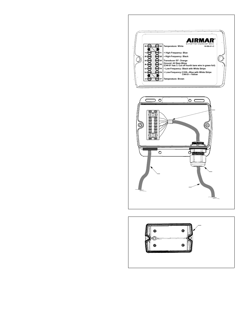
Connecting
CAUTION: When the connections are complete, be sure there are
no frayed strands, or loose or bare ends to cause shorting.
1. Remove the cover of the Diplexer. Set it aside along with the
two
screws and the plastic bag containing the four mounting screws.
2. Push approximately 200mm (8") of the transducer cable
through the compression nut (see Figure 1). To ease sliding,
bend the wires back against the cable jacket or wrap electrical
tape around them.
3. C44-01 Cable Only—Select the bundle wrapped in green foil,
containing brown, white, and bare wires. Cut off the bare wire
and the foil flush with the cable jacket.
4. Protect the cable’s foil shielding from causing a short circuit
inside the Diplexer. Use heat-shrink tubing around the jacket
where the wires emerge from the cable. The tubing must
overlap the wires a minimum of 6mm (1/4").
5. Twist the bare wires together.
C44-01 has 3 bare wires. (A fourth bare wire was cut off.)
C335 has 2 bare wires.
6. Following the label on the Diplexer cover and the list below,
insert the stripped end of each colored wire /twisted bare wires
into the appropriate opening in the side of the terminal block.
Tighten the terminal screw until the wire(s) is held firmly.
1.
Brown
Temperature
2.
Yellow (C44-01 cable)
+ Low frequency
Blue with white stripe (C335 cable)
3.
Black with white stripe
- Low frequency
4.
Bare wires
Ground
(C44-01 has 3 bare wires. The fourth bare was cut off.)
(C335 has 2 bare wires)
5.
Orange
Transducer ID®
6.
Black
- High frequency
7.
Blue
+ High frequency
8.
White
Temperature
7. Visually inspect all the wires. There should be no frayed strands
or loose ends to cause shorting. If any colored wire has a visible
bare end, reconnect it to the terminal.
Completing the Installation
1. From outside the Diplexer, pull the transducer cable until only
51mm (2") of jacket remains inside the box. Using slip-joint
pliers, tighten the compression nut to make a watertight seal.
2. Arrange the wires neatly inside the Diplexer. Check to be sure
the gasket is firmly installed in the channel on the back side of
the cover (see Figure 2). Lubricate the gasket with petroleum
jelly. Screw the cover in place with the two long screws
supplied.
3. Fasten the Diplexer in place at the mounting location with the
four 6 x 1/2" screws supplied.
4. Plug the connector on the fishfinder cable into the Diplexer
cable connector.
5. Fasten all the cables in place. Coil any excess cable and
secure it with cable ties to prevent damage.
Figure 1. Connecting
Copyright © 2009 Airmar Technology Corp.
2
compression
Diplexer cable
connects to fishfinder
transducer
cable
AIRMAR
®
TECHNOLOGY CORPORATION
35 Meadowbrook Drive, Milford, New Hampshire 03055-4613, USA
www.airmar.com
Copyright © 2009 - 2010 Airmar Technology Corp. All rights reserved.
heat-shrink
tubing
NOTE: lubricate
gasket with
petroleum jelly
Figure 2. Lubricate the gasket
Copyright © 2009 Airmar Technology Corp.
nut
(enlarged to show detail)
Transducer ID® is a trademark of Airmar Technology Corporation.