Preparing the cables, A. one cable (zip-cable) multisensor – Airmar B744V User Manual
Page 2
Preparing the Cables
A. One Cable (Zip-cable) Multisensor
CAUTION: Do not cut the depth-transducer half of the zip-cable.
CAUTION: Do not puncture unused grommets.
1. Disconnect the multisensor from the echosounder.
2. On the junction box, use a small Phillips screwdriver to
puncture the center of both grommets marked 5-7 and one
grommet marked 3-5 (see Figure 2).
3. The multisensor’s cable is actually two separate cables joined
together. This type of cable is called zip-cable. Near the
mounting location of the junction box, separate the two halves of
the zip-cable. Carefully cut them apart with a box-cutter knife for
a distance of 0.5m (18"). Start at the junction box location and
move toward the sounder. Cut only the insulation between the
halves. DO NOT cut into the cables and expose the wires inside.
4. After you have separated the zip-cable, notice that one of the
halves is printed with the words “Airmar Transducer Cable” (see
Figure 3). The printed half of the zip-cable contains the speed
and temperature functions. Cut only the speed/temperature
half of the cable near the junction box. The wires inside will
be red and green. DO NOT cut the depth-transducer half of the
cable.
NOTE: If the wires inside the cut-half of the cable are blue,
black, and orange, you have cut the depth-transducer side by
mistake. Now cut the speed/temp half of the zip-cable. Because
the depth-transducer cable has been cut, you will need to splice
it back together (see Figure 9). Puncture the center of the
remaining 3-5 grommet. Prepare the cut ends of the depth-
transducer cable (see Figure 10). If you have a nine or ten wire
cable, use crimping pliers and the crimp connectors supplied.
Also use silicone lubricant or petroleum jelly to ease sliding
through the grommets.
5. Label the cables as follows with tape and a marker (see Figure 2).
• Cable A—cable to echosounder
• Cable B—cable to multisensor
• Cable C—new speed/temp insert cable
6. Cables A and B—Strip 6cm (2-1/2") of the outer jacket and foil
shield from the cut ends (see Figure 4).
7. Cable A—Strip 13mm (1/2") of insulation from the end of each
colored wire.
8. Cable B—Only the bare wire will be used. Cut-off all the colored
wires.
9. Bend the stripped wires of each cable back against its cable
jacket (see Figure 5). Apply alcohol to the cut end of each cable
jacket to ease sliding. (Do not use any other lubricant to ease
sliding. It will interfere with sealing the grommets.) Push about
20cm (8") of each cable through the appropriate grommet until
all the wires are inside the junction box (see Figure 2). Bend the
wires back to their original position (see Figure 5).
10.Slide a black sleeve over each bare wire and position it against
the cable jacket. For ease in holding the sleeves in place and
connecting to the terminals, fold the stripped ends of each wire
in half. Twist the ends and bend them 90
°
(see Figure 4).
11.Go to “Connecting & Testing” on page 3 and follow the
instructions.
2
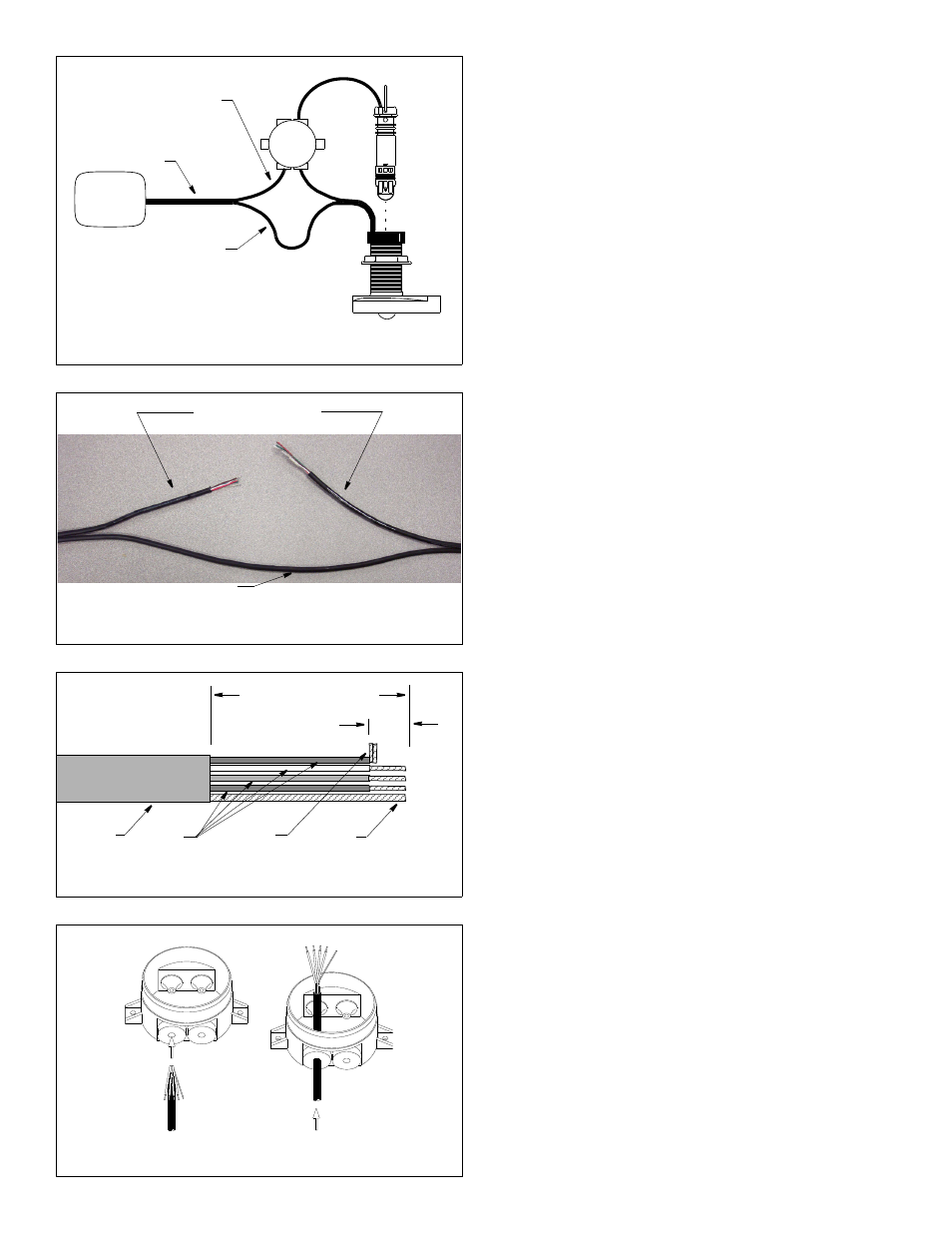
Figure 5. Pushing a cable through a grommet
5 -7
echosounder
Figure 2. Splicing a zip-cable multisensor
speed/temp half of zip-cable
(printed half)
(contains red, green, brown,
white, and bare wires)
depth-transducer
5 -7
5 -7
5 -7
half of zip-cable
Figure 4. Preparing the cables
cable
jacket
AIRMAR TRANSDUCER CABLE C344
colored
wires
bare
wire
folded
stripped end
Copyright © 2002, 2009 Airmar Technology Corp.
Figure 3. Cutting the speed/temperature half of a zip-cable
6cm (2 1/2")
remove outer jacket and foil shielding
13mm
(1/2")
B
A
C
zip-cable
3-5
5-7
5-7
Cut the half of the
“Airmar Transducer Cable”
zip-cable that is labeled
Do not cut the
unmarked half
multisensor
insert
Copyright © 2002, 2009 Airmar Technology Corp.
Copyright © 2002, 2009 Airmar Technology Corp.
Copyright © 2002, 2009 Airmar Technology Corp.