Antifouling paint – Airmar B744V User Manual
Page 2
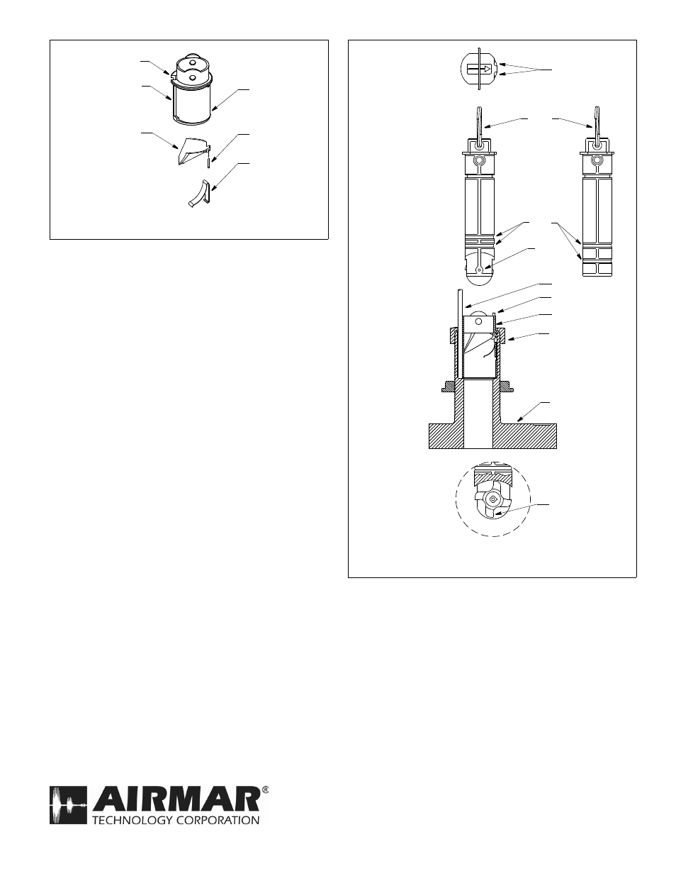
4. Check the new valve assembly to see that the flap valve moves
freely and seats against the sleeve (see Figure 4). Discard the
old valve assembly.
5. To service the paddlewheel insert, use the new paddlewheel
shaft to push the old shaft out about 6mm (1/4"). With pliers,
remove the old shaft (see Figure 5).
6. Remove any aquatic growth from the insert using a stiff brush or
putty knife. Clean the surface with mild household detergent
and a Scotch-Brite® scour pad. If fouling is severe, lightly wet
sand it with fine grade wet/dry paper.
7. Place the new paddlewheel in the cavity with the flat side of the
blade facing the same direction as the arrow on the top of
the insert.
8. Tap the new shaft into place until the ends are flush with the
insert.
9. Replace the two O-rings in the groves near the paddlewheel.
Do not place them near the pull ring. Lubricate the O-rings with
silicone lubricant or petroleum jelly (Vaseline®).
10.Slide the paddlewheel insert into the valve assembly. Seat it
into place with a twisting motion until the keys fit into the
notches. Secure the paddlewheel insert with the retaining pin
and safety ring(s) (see Figures 2 and 3).
11.Reinstall the valve assembly by first removing the safety wire
from the blanking plug. With the valve assembly/insert ready in
one hand, remove the blanking plug. Slide the valve assembly
into the multisensor housing with the arrow on the top pointing
forward toward the bow. Be sure the cable fits into the cable
channel and the key in the housing fits into the notch in the
sleeve (see Figure 4). (A pushing twisting motion will locate the
key.) Screw the cap nut in place. Be careful to avoid cross
threading the cap nut. Hand-tighten only. Do not over tighten.
12.Always attach the safety wire to prevent the insert from
backing out in the unlikely event that the cap nut and/or insert
nut fails or is screwed on incorrectly. Reattach the safety wire
(see Figures 2 and 3).
2
Figure 5. Servicing
(B744V shown)
BOW
►
flat side of
paddlewheel
O-rings
paddlewheel
pull ring
shaft
cap nut
paddlewheel
top view of
housing and
blade faces
paddlewheel
insert
insert
valve assembly
housing
notches
key (2)
valve
assembly
insert detail
cable
blanking
plug
direction of
arrow on top
of insert
(toward bow)
Antifouling Paint
Surfaces exposed to salt water must be coated with antifouling
paint. Use water-based antifouling paint only. Never use ketone-
based paint, since ketones can attack many types of plastic
possibly causing damage. Paint the following surfaces.
• Exposed areas of the housing including the transducer’s face
• Bore of the housing up 30mm (1-1/4")
• Outside wall below lower O-ring of paddlewheel insert
• Paddlewheel cavity
• Paddlewheel
• Blanking plug below lower O-ring including exposed end
Figure 4. Valve assembly
(B744V shown)
sleeve
flap valve
spring pin
spring
notch
cable channel
Copyright © 2005 Airmar Technology Corp.
Copyright © 2005 Airmar Technology Corp.
Copyright © 2005 - 2014 Airmar Technology Corp. All rights reserved.
35 Meadowbrook Drive, Milford, New Hampshire 03055-4613, USA
•
www.airmar.com